|
|
||
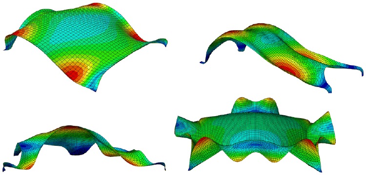
Fig. 10: First mode shapes of shell 2 (top-left), 3 (top-right), 5 (bottom-left) and 8 (bottom-right)
From the same paper as the previous image.
The authors write:
“Buckling and frequency analysis:
This section evaluates the resistance of Isler’s shells to buckling. The buckling and frequency analysis of shells require modelling of exact support details, however, only for the purpose of a comparative evaluation of shells, identical support conditions are assumed for them. Under these assumptions, shells number 1, 7 and 8 had acceptable buckling loads, whereas in other shells, particularly in shells obtained by the hanging method, such as shell 3, this type of failure was probable. Additionally, the buckling is calculated for (uniformly distributed) dead load only, however, by adding snow or wind loads, due to their anti-symmetrical nature, the shells will be more susceptible to buckling. In some shells such as shell number 1, which is surrounded by supports all around, and has a relatively higher thickness to span ratio, buckling is not a prime concern. The buckling failure was Isler’s major concern in design of shells that is why in some projects he added extra elements such as cables near the supports as a source of pre-stressing and restraining the supports from moving and highly strengthened them. In addition to buckling, the modal analysis was performed for the shells, which indicated that the highest eigenvalue and the lowest period time belong to shells 1, 7, 8 and 6, respectively. The analysis also shows a sequence of symmetrical mode shapes in almost all of the shells. Figure 10, shows different modal behaviour of shells 2, 3, 5 and 8.
Page 90 / 114