|
|
||
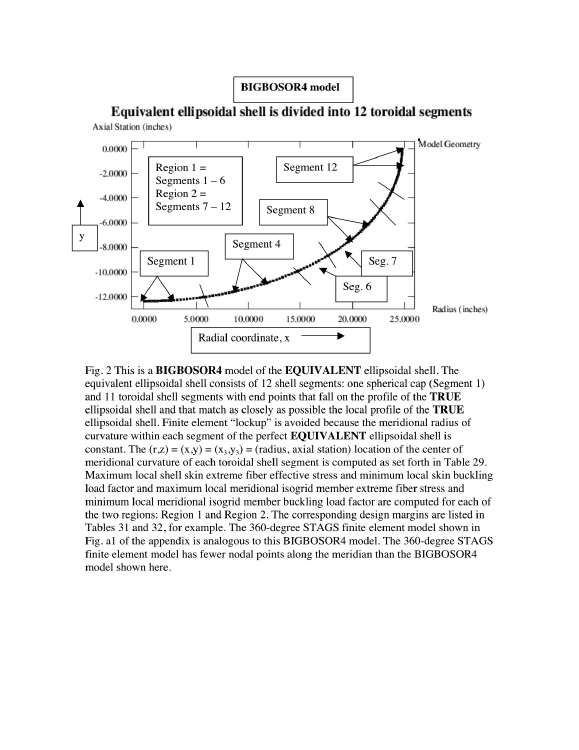
This is Fig. 2 from the 2009 GENOPT paper, "Minimum weight design of imperfect isogrid-stiffened ellipsoidal shells under uniform external pressure" by David Bushnell, presented at the AIAA 50th Structures, Structural Dynamics, and Materials Conference, Palm Springs, California, 2009, AIAA Paper 2009-2702.
Shown here is a BIGBOSOR4 model of the EQUIVALENT ellipsoidal shell. The equivalent ellipsoidal shell consists of 12 shell segments: one spherical cap (Segment 1) and 11 toroidal shell segments with end points that fall on the profile of the TRUE ellipsoidal shell and that match as closely as possible the local profile of the TRUE ellipsoidal shell.
Finite element “lockup” is avoided because the meridional radius of curvature within each segment of the perfect EQUIVALENT ellipsoidal shell is constant. The (r,z) = (x,y) = (x3,y3) = (radius, axial station) location of the center of meridional curvature of each toroidal shell segment is computed as set forth in Table 29 of the 2009 GENOPT paper cited above.
Maximum local shell skin extreme fiber effective stress and minimum local skin buckling load factor and maximum local meridional isogrid member extreme fiber stress and minimum local meridional isogrid member buckling load factor are computed for each of the two regions: Region 1 and Region 2. The corresponding design margins are listed in Tables 31 and 32 of the 2009 GENOPT paper.
See the "GENOPT" slide show for more details on this interesting optimization problem in which GENOPT is used for optimization with BIGBOSOR4 as the structural analyzer.
Page 21 / 36