|
|
||
This and the next 9 images show compound shells, models of them and predictions of buckling and modal vibration from analyses by David Bushnell conducted with the use of the computer programs, BOSOR4/BIGBOSOR4.
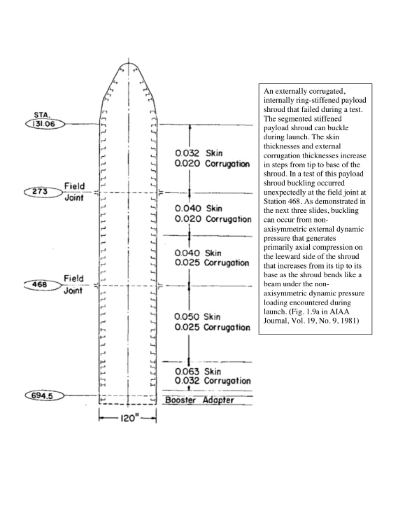
This is Fig. 1.9(a) from the paper, "Buckling of Shells - Pitfall for Designers", by David Bushnell, AIAA Journal, Vol. 19, No. 9, September 1981.
This and the next 3 slides pertain to the same geometry and loading. The analysis was performed by the BOSOR4 computer program for the stress, buckling and vibration analysis of shells of revolution, now superseded by BIGBOSOR4. (BIGBOSOR4 solves configurations with many more shell segments than BOSOR4 and also finds buckling loads of prismatic panels as well as shells of revolution.)
This slide shows an externally axially corrugated, internally ring-stiffened payload shroud that failed unexpectedly during a test. This and the next 3 slides pertain to this example.
The skin thicknesses and external corrugation thicknesses increase in steps from tip to base of the shroud.
The segmented stiffened payload shroud can buckle during launch because of beam-type bending of the shroud under the non-axisymmetric dynamic pressure loading as the rocket passes through the atmosphere during launch.
In a test of this payload shroud early buckling occurred unexpectedly at the field joint at Station 468. As demonstrated two slides hence, buckling can occur from non-axisymmetric external dynamic pressure that generates primarily axial compression on the leeward side of the shroud, compression that increases from its tip to its base as the shroud bends like a beam under the non-axisymmetric dynamic pressure loading encountered during launch through the atmosphere.
Page 15 / 216