|
|
||
From:
"Optimization of Propellant Tanks Supported by Optimized Laminated Tubular Struts" by David Bushnell, Michael S. Jacoby and Charles C. Rankin, 54th AIAA Structures Meeting, Boston, MA, April 8-12, 2013
ABSTRACT: The propellant tank is a shell of revolution completely filled with liquid hydrogen (LH2). This propellant tank is to be launched into space. During launch it is subjected to high axial and lateral accelerations. The tank is supported by a system of struts that consist mainly of tubes with laminated composite walls. This strut-supported tank system is optimized via GENOPT/BIGBOSOR4 in the presence of two loading cases: (1) 10 g axial acceleration and 0 g lateral acceleration and (2) 0 g axial acceleration and 10 g lateral acceleration. In addition to the g-loading the tank has 25 psi internal ullage pressure and the tank wall is 200 degrees cooler than the wall of the launch vehicle from which it is supported by the struts. In the BIGBOSOR4 modal vibration model the mass of the propellant is "lumped" into the tank wall, a conservative model. The tank/strut system is optimized in the presence of the following constraints: (1) the minimum modal vibration frequency must be greater than a given value; (2) five stress components in each ply of the laminated composite wall of the strut tubes shall not exceed five specified allowables; (3) no strut tube shall buckle as a column; (4) no strut tube shall buckle as a thin cylindrical shell; (5) the maximum effective (vonMises) stress in the tank wall shall not exceed a specified value; (6) the tank wall shall not buckle; (8) the maximum force in a strut during the launch-hold phase of a mission shall not exceed a specified value. The objective to be minimized is in general a weighted combination of the normalized mass of the empty tank plus the normalized conductance of the support system: Objective= W x (normalized empty tank mass) + (1-W) x (normalized strut conductance), in which W is a user-selected weight between 0.0 and 1.0. Two propellant tank/strut systems are optimized: (1) a long tank with two "rings" of struts, an aft ring and a forward ring, and (2) a short tank with only one "ring" of struts. It is emphasized that the tank/strut combination is optimized as a single system. The flexibility of the propellant tank is accounted for and found to be significant for optimized tank/strut systems. The flexibility of the launch vehicle to which the tank/strut system is attached is neglected: the ends of the supporting struts attached to the launch vehicle are assumed to be attached to rigid "ground". Parameter studies are conducted in which optimum designs are obtained as a function of the number of strut pairs attached to the tank. During optimization linear theory is used throughout. Predictions for certain of the optimized tank/strut designs obtained here are compared with those from the general-purpose finite element code, STAGS. The agreement between the predictions of GENOPT/BIGBOSOR4 and STAGS qualifies the use of GENOPT/BIGBOSOR4 for preliminary design in the particular cases studied here.
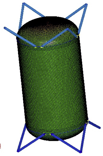
This slide shows the STAGS finite element model of the optimized long propellant tank with two sets of struts, aft (Lower) and forward (Upper), with 4 pairs of struts at each axial location. The struts are pinned to the centroids of the aft and forward propellant tank external support rings and to rigid “ground”. The STAGS “410” finite element is used in the model of the propellant tank shell wall.
Page 3 / 216