|
|
||
From the same paper as the previous four slides.
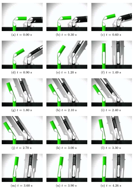
Starting from a state in which there exists a relative angle of 90 degrees between two adjacent “rigid” segments (a), the “hinged” rod first straightens (b - f), then overshoots (g - i), then straighens again (j - l). then overshoots slightly in the opposite sense (m - n), and finally returns to the straight (deployed) state (o).
Details of static bending behavior of each of the two free-edged cylindrical sectors in the “hinge” region are shown three slides ago. As shown in that slide, each of these two free-edged shallow cylindrical sectors, bending in opposite directions, behave locally like a tape measure with a curved shallow cylindrical cross section being bent first one way then the other way. As shown three slides ago, the behavior (moment-rotation relationship) of each of the two shallow cylindrical sectors is highly nonlinear, high-energy snapping occurring when bending is in a direction such that the mid-width of the shallow cylindrical sector is under axial compression, and low-energy snapping occurring when bending is in the opposite direction.
Page 45 / 216