|
|
||
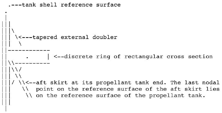
from the 2013 GENOPT paper2. The geometry of each tank/skirt junction is similar, but not the same as that shown in the sketch near the beginning of [1] and repeated here with appropriate modification and with the word, “strut”, replaced by the word, “skirt”. This slide shows a sketch of the propellant tank wall with a local reinforcement at the axial location where the tank-end of the aft conical skirt is attached to the reference surface of the propellant tank. Note: in this sketch the innermost "layer" of the propellant tank, which consists of an orthogrid with "smeared" stringers and rings, is not shown.
[1] "OPTIMIZATION OF PROPELLANT TANKS SUPPORTED BY OPTIMIZED LAMINATED COMPOSITE TUBULAR STRUTS", by David Bushnell, Mike Jacoby and Charles Rankin, Unpublished paper, September 2012
Page 116 / 190