|
|
||
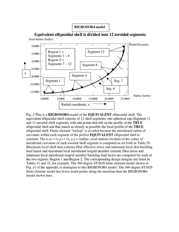
This is Fig. 2 from the 2009 GENOPT paper. Shown here is a BIGBOSOR4 model of the EQUIVALENT ellipsoidal shell.
The equivalent ellipsoidal shell consists of 12 shell segments: one spherical cap (Segment 1) and 11 toroidal shell segments with end points that fall on the profile of the TRUE ellipsoidal shell and that match as closely as possible the local profile of the TRUE ellipsoidal shell. Finite element “lockup” is avoided because the meridional radius of curvature within each segment of the perfect EQUIVALENT ellipsoidal shell is constant.
The (r,z) = (x,y) = (x3,y3) = (radius, axial station) location of the center of meridional curvature of each toroidal shell segment is computed as set forth in Table 29 of the 2009 GENOPT paper.
Maximum local shell skin extreme fiber effective stress and minimum local skin buckling load factor and maximum local meridional isogrid member extreme fiber stress and minimum local meridional isogrid member buckling load factor are computed for each of the two regions: Region 1 and Region 2.
The corresponding design margins are listed in Tables 31 and 32 of the 2009 GENOPT paper.
The 360-degree STAGS finite element model shown in Fig. a1 of the appendix of the 2009 GENOPT paper (see the next slide) is analogous to this BIGBOSOR4 model. The 360-degree STAGS finite element model has fewer nodal points along the meridian than the BIGBOSOR4 model shown here.
Page 33 / 190