|
|
||
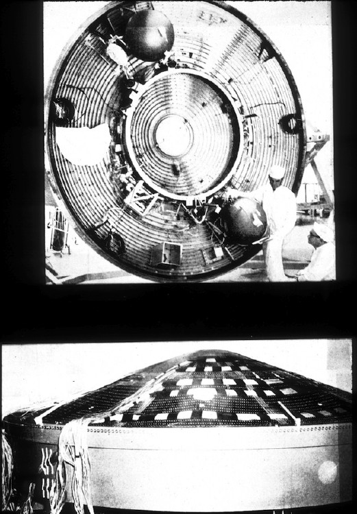
This and the next 2 images are either from the Cohen paper cited below or from papers written by researchers who used FASOR to analyze the shells shown here. For example, this image is from:
Walter L. Heard, Jr., Melvin S. Anderson and Wendell B. Stephens, "The effect of ring distortions on buckling of blunt conical shells", NASA TN D-7853, February 1975
The FASOR computer program was created by Gerald A. Cohen during the 1970s.
Gerald A. Cohen (Structures Research Associates, Laguna Beach, California, USA),
“FASOR — a program for stress, buckling and vibration of shells of revolution”, Advances in Engineering Software (1978), Vol. 3, No. 4, October 1981, pp.155-162, doi:10.1016/0141-1195(81)90013-9
ABSTRACT: FASOR (Field Analysis of Shells of Revolution) is a user-oriented code for the analysis of stiffened, laminated axisymmetric shells. Very general shell geometries are allowed in that the reference surface meridian may form a branched, multi-circuit figure. Modes of response treated are linear asymmetric and geometrically nonlinear axisymmetric prebuckling, and asymmetric buckling and vibration under static axisymmetric loads. Bifurcation buckling under asymmetric loads is also treated by using a symmetrized prebuckling state based on the linear response of a user-specified meridian. For each mode of response, the user may specify any combination of orthotropic or anisotropic material properties with classical or transverse shear deformation shell theories. FASOR employs a numerical integration method (called the field method) whereby a numerically unstable linear boundary-value problem (all modes of response reduce to a sequence of such problems) is converted into two successive numerically stable initial-value problems. In this context, numerical stability means that round-off errors introduced at each step of the integration process tend to decay out. As a consequence, solution accuracy is controlled essentially by a single number, the truncation error tolerance, which is satisfied by automatically adjusting the size of each integration step. The field method thus eliminates the need for mesh generation required by finite element and finite difference methods, and the associated problem of numerical convergence. It also provides for automatic determination of response storage points so as to obtain a uniformly valid discrete approximation of the continuous response. In this paper the field method is briefly described, basic aspects of the mathematical model are discussed, the organization of input data is presented, and input and plot output are given for specific examples.
Page 6 / 256