|
|
||
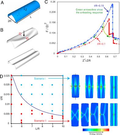
FIGURE 2: Indentation of a cylindrical shell. (A) Schematic of a semicylindrical shell with radius R and length L, clamped along the lateral edges with free ends. The ends of the shell are free to displace and rotate and the shell is indented at its center. (B) The deformed configuration of the shell (L/R = 6, t/R = 0.15) shows an abrupt transition from a complex deformation pattern to a simple planar deformation mode as the indentation is increased from Z′ = Z/R = 0.67 (Upper) to Z′ = 0.68 (Lower). (C) Force–indentation response of a semicylindrical elastic shell with L/R = 6. For the shell with t/R = 0.15, both loading and unloading responses are plotted, and are again hysteretic. (D) Two possible transition pathways from a semicylindrical shell to the final developable surface. The results are for shells with L/R = 6 and t/R = 0.15 (Upper Right) and t/R = 0.1 (Lower Right), the latter of which has been observed experimentally (16).
From the same paper as cited in the previous slide.
Page 134 / 410