|
|
||
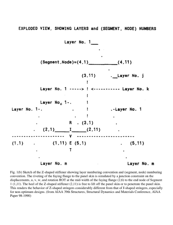
Fig. 1b of the 1998 zstiffener paper. This slide shows a
sketch of the Z-shaped stiffener showing layer numbering convention and (segment, node) numbering convention.
The riveting of the faying flange to the panel skin is simulated by a junction constraint on the displacements, u, v, w, and rotation ROT at the mid-width of the faying flange (Segment 2, Nodal point 6) to the end node of Segment 1 (Segment 1, Nodal point 11).
The toe and heel of the Z-shaped stiffener (2,1 and 2,11) are free to lift off the panel skin or to penetrate the panel skin as the skin deforms. (There is no "contact" element in PANDA2.)
This renders the behavior of Z-shaped stringers considerably different from that of J-shaped stringers in which the faying flange is bonded to the panel skin along the entire width of the faying flange, especially for non-optimum designs.
Page 31 / 38