|
|
||
This and the next three slides are from: "Use of GENOPT and BIGBOSOR4 to obtain optimum designs of an axially compressed cylindrical shell with a composite truss-core sandwich wall" by David Bushnell and Charles Rankin, AIAA 52nd Structures, Structural Dynamics, and Materials Conference, 2011, AIAA Paper 2011-1811, referred to as "2011 GENOPT paper" in the next three slides.
ABSTRACT: GENOPT/BIGBOSOR4 is applied to the problem of an axially compressed perfect elastic cylindrical shell the wall of which is a laminated composite truss-core sandwich. The truss-core sandwich is constructed of trapezoidal core tubes that are sandwiched between two face sheets. At the junction of the core webs and the face sheets are “noodle” regions ("noodle gaps" that are filled with unidirectional composite material.
The design constraints are local buckling, general buckling, and five stress constraints for each material. Local and general buckling are computed from BIGBOSOR4 models in which the "true prismatic" representation of the cylindrical shell is employed.
In both the local and general buckling models the "true prismatic" representation of the cylindrical shell consists of a number of identical modules of the cross section of the truss-core sandwich wall that are strung together along the curved meridian of the "true prismatic" shell.
The rather elaborate 22-segment module used for local buckling includes small curved and straight segments that occur at the corners of the trapezoidal tool around which the truss-core is wrapped during the fabrication process.
The presence of "noodles" that fill the prismatic triangular-like gaps between adjacent trapezoids is accounted for. BIGBOSOR4 models are included that determine approximately the effect on local buckling of support by each noodle of the little shell segments that enclose it.
The six-segment module used for general buckling is much simpler than the 22-segment module used for local buckling. It consists of six shell segments analogous to those used in the truss-core sandwich model employed in PANDA2. The effect of the "noodles" is accounted for, however, which is not possible in the PANDA2 model.
(A multi-module model consisting of a number of six-segment single modules is displayed two slides hence.)
The GENOPT/BIGBOSOR4 general buckling model retains both face sheets and truss-core webs as flexible shell segments. Therefore, the general buckling model exhibits the correct global transverse shear deformation (t.s.d.) characteristics, whereas in PANDA2 the effect of t.s.d. is simulated approximately by a knockdown factor.
The number of modules used in the model for general buckling is determined by the largest circumferential arc that subtends the maximum number of shell segments permitted by BIGBOSOR4: 295 segments.
Stress constraints are computed in a way completely analogous to that used in PANDA2 for composite laminates, but calculations are simpler because the pre-buckled state of the "true prismatic" shell is a uniform membrane state whereas local bending due to initial imperfections is permitted in the PANDA2 model.
The effect of thermal curing is included in the model.
The decision variables for optimization are the width of a single module, the width of the crown of one trapezoid, the height of the trapezoid, two distinct corner radii of the trapezoidal core tube, and lamina thicknesses. Optimum designs are obtained via SUPEROPT.
The objective is the weight per unit area of the cylindrical shell.
Predictions from GENOPT/ BIGBOSOR4 are compared with those from PANDA2. Local and general finite element models for processing by STAGS are automatically produced by GENOPT/BIGBOSOR4 for the truss-core sandwich configurations previously optimized by GENOPT/BIGBOSOR4.
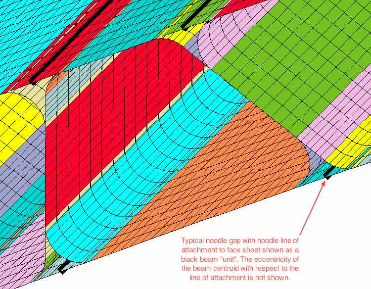
This is Fig. 18 from the 2011 GENOPT paper. This slide shows part of a STAGS model for the specific case called “nasatruss2” (Table 3 of the 2011 GENOPT paper identified above).
This is a close-up view of a STAGS finite element model of one of the local buckling modules. Each shell unit in the STAGS local buckling model is shown here in a different color.
The black “units” represent the noodles. Unfortunately, STAGS does not show the eccentricity of the noodle centroid with respect to its attachment point of the face sheet. However, this eccentricity is present and accounted for in the STAGS model.
The STAGS input file, *.inp, is automatically created by the generic GENOPT/BIGBOSOR4 case called "trusscomp" and the specific case called "*", in which "trusscomp" is the generic case name selected by the GENOPT user and "*" stands for the end-user-selected specific case name.
Comparisons between results from GENOPT/BIGBOSOR4 and general purpose computer programs such as STAGS are provided in Ref. [1] listed in the Reference section of the 2011 GENOPT paper.
Page 65 / 180