|
|
||
NOTE: Fig. 37 is shown in the next image.
FROM:
David Bushnell and Michael S. Jacoby, “Minimum weight design of an axially compressed isotropic prismatic panel consisting of a series of cylindrical segments and verification by STAGS”, AIAA Paper 2014-0844, AIAA 55th Structures, Structural Dynamics and Materials Meeting, January 13-17, 2014, National Harbor, Maryland (Part of SCITECH 2014 Conference)
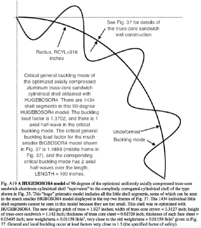
ABSTRACT: We want to determine the minimum amount of material required to span a distance of width = WIDTH for an axially compressed, unstiffened, prismatic metallic wall or panel of length = LENGTH. The prismatic panel has a complex “corrugated” cross section. The width of the complex “corrugated” panel is composed of a number of “major” cylindrical segments, each of which may be divided into a number of cylindrical “sub-segments”. Each segment and each sub-segment is a sector of a little cylindrical shell the generators of which run in the axial direction. In addition there exists an overall arching over the entire width of the panel. The several little cylindrical segments/sub-segments are joined generator to generator in series. The entire unstiffened “corrugated” panel can be fabricated without any welding. Half of the width of the panel is included in the BIGBOSOR4 model used for optimization, with symmetry and anti-symmetry conditions imposed at its mid-width, WIDTH/2. The GENOPT/BIGBOSOR4 system is used to build the model and to perform the optimization. The minimum weight of the panel is determined in the presence of the following behavioral constraints: 1. The panel shall not buckle locally, 2. The panel shall not buckle in a general mode that is symmetric at the plane of symmetry, 3. The panel shall not buckle in a general mode that is anti-symmetric at the plane of symmetry, 4. Each little cylindrical segment of the panel shall not buckle in a “classical” mode, and 5. The maximum stress in the wall of the panel shall be less than a specified value. The numerical analysis is extended to flat or curved panels of any width with repeating complex cross sections. An optimized cross-section profile with reflected and multiple repeating complex sections is mapped onto a cylindrical surface, and the buckling characteristics and weight of this complexly corrugated cylindrical shell are compared with those of an optimized “equivalent” cylindrical shell with external T-shaped stringers, an “equivalent” optimized cylindrical shell with a truss-core sandwich wall, and an optimized “equivalent” cylindrical shell with uniform corrugations. It is found that the optimized complexly corrugated cylindrical shell weighs less than these other three optimized “equivalent” cylindrical shells that have different wall constructions. Optimized complexly corrugated panels with cylindrical segments the geometry of which varies across its width weigh about 12-14 per cent less than optimized uniformly corrugated panels, such as a standard corrugated panel. The existence of sub-segments does not lead to panels that weigh less than panels without sub-segments. The gradient-based optimizer used in the GENOPT/BIGBOSOR4 system (“ADS” by Vanderplaats) has difficulty finding “global” optimum designs for panels with many cylindrical segments. Several of the optimized designs determined with GENOPT/BIGBOSOR4 are verified by comparison with predictions from the general-purpose computer program STAGS. The agreement between the predictions of GENOPT/BIGBOSOR4 and STAGS qualifies the use of GENOPT/BIGBOSOR4 for optimization in the particular cases studied here. The behavior of optimized configurations with “corners” (discontinuous slope in the “width-wise” direction) between major cylindrical segments are compared with that of configurations in which these “corners” have been smoothed by the introduction of transitional fairing segments. A program called HUGEBOSOR4 is developed to handle cases with up to 2950 segments.
Page 70 / 180