|
|
||
From the same paper as the previous slide.
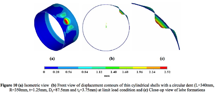
Figure 10(a) shows the isometric view of displacement contours at limit load condition and it can be seen that as expected the deformation is maximum at dent geometry and the displacement below the dent gradually becomes zero towards supporting edge. Due to the presence of dent, the displacement contours in and around the DER is getting distorted. Figure 10(b) shows lobe formations of ridges and dent geometry in front view at limit load condition.
Page 250 / 444