|
|
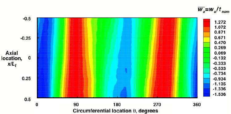
||
x = axial coordinate
L-sub-t is the length of the cylindrical shell
W-sub-zero is the amplitude of the imperfection
t-sub-nom = nominal wall thickness
This slide supplied by Michael Nemeth, NASA Langley Research Center, Hampton, Virginia
This is Fig. 4 from the report:
Mark W. Hilburger, Michael P. Nemeth and James H. Starnes, Jr., "Shell buckling design criteria based on manufactoring imperfection signatures", NASA/TM-2004-212659, May 2004.
ABSTRACT: An analysis-based approach for developing shell-buckling design criteria for laminated-composite cylindrical shells that accurately accounts for the effects of initial geometric imperfections is presented. With this approach, measured initial geometric imperfection data from six graphite-epoxy shells are used to determine a manufacturing-process-specific imperfection signature for these shells. This imperfection signature is then used as input into nonlinear finite-element analyses. The imperfection signature represents a "first-approximation" mean imperfection shape that is suitable for developing preliminary-design data. Comparisons of test data and analytical results obtained by using several different imperfection shapes are presented for selected shells. Overall, the results indicate that the analysis-based approach presented for developing reliable preliminary-design criteria has the potential to provide improved, less conservative buckling-load estimates, and to reduce the weight and cost of developing buckling-resistant shell structures.
Page 43 / 444