|
|
||
from the website:
http://www.smr.ch/local/doc/B2000++/test_cases/ch03s02.xhtml
The authors (anonymous) of the web site write:
"Post-buckling analysis of axially compressed cylinders presents considerable difficulties to the nonlinear solution procedure: Since the structure fails radically (collapse), the analytical solution procedure has to cope with energy dissipation. Here, this is achieved by selecting load-control with artificial damping. Another problem is the presence of many solution paths: A slightly different response in the vicinity of bifurcation points can result in a quite different buckling pattern at the final load and accordingly different reaction forces. Finally, the curved geometry requires the use of efficient shell elements. Thus, this case can serve as a benchmark for the reliability and numerical effectiveness of the elements and nonlinear solver.
The observed discrepancy between the analytically or numerically predicted buckling load and the experimentally determined buckling load - the so-called knock-down factor [1],[2],[4] - is mainly due to geometric (manufacturing) imperfections, but also due to fluctuations in applying the compressive load. The single perturbation concept developed by Hühne [1] presents a practical way to obtain a lower bound for the buckling load. It is used here by applying at the entire section a concentrated perturbation force in radial direction. Reference values for load-displacement curves are extracted from [1].
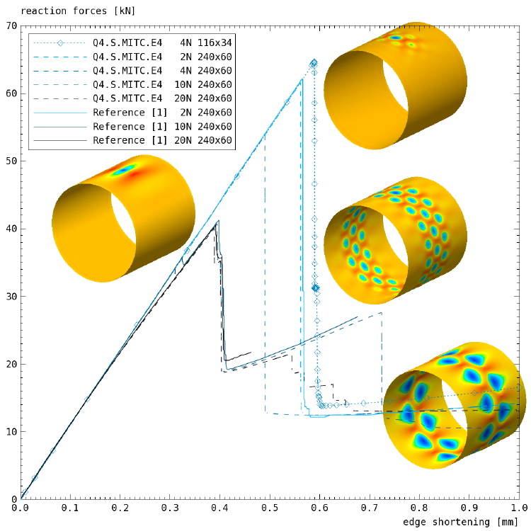
The radius of the cylinder is 0.25 [m], the length is 0.5 [m], and the thickness is 0.5 [mm]. For the automatic test case, the mesh consists of 116 Q4.S.MITC.E4 shell elements in circumferential direction and 34 elements in axial direction. This mesh density is actually too coarse but was chosen to obtain acceptable solution times for the automatic test procedure. Sufficiently fine meshes consist of 240 elements in circumferential direction and 60 elements in axial direction; this is also the mesh density used in [1]. All nodes have a local coordinate system, with the x-axis in radial direction, the y-axis in circumferential direction, and the z-axis in axial direction. The material is Aluminium (E=70.e9 [Pa], p=0.33), but support for many different composite laminates is built into the generating script.
The boundary conditions are applied in two stages. In the first stage, while the bottom is clamped and the top is -- except for the axial direction -- clamped, too, the perturbation load is applied. For the automatic test case, a value of 4 [N] is used (reference curves are available for values of 2, 10, and 20 [N]). In the second stage, the top is displaced -0.001 [m] in axial direction.
Load-displacement curves for different mesh densities and different perturbation loads are shown in this slide. The automatic test succeeds if the obtained load-displacement curve matches to the first curve shown in the slide."
References:
[1] H. Wang, A. P. Bueschel, R. Degenhardt, K. Rohwer, X. Sun, W. Wagner, An empirical formula for the critical perturbation load
http://www.cocomat.de/Endmeeting/Abstracts/50-COCOMAT_Wang.pdf
[2] C. Hühne, R. Rolfes, E. Breitbach, J. Teßmer, Robust design of composite cylindrical shells under axial compression — Simulation and validation, Thin-Walled Structures Volume 46, Issues 7-9, July-September 2008, Pages 947-962
[3] H.-R. Meyer-Piening, M. Farshad, B. Geier, R. Zimmermann, Buckling loads of CFRP composite cylinders under combined axial and torsion loading -- experiments and computations, Composite Structures 53 (2001) 427-435
[4] NASA SP-8007, 1968: Buckling of thin-walled circular cylinders
Page 51 / 444