|
|
||
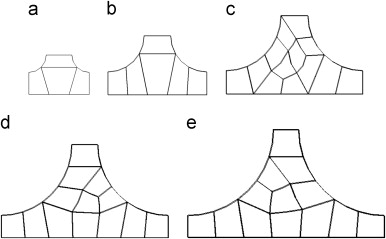
Cross sections of 5 filleted junctions for the finite element analysis. The cross sections show only the filleted portions of the junction. (a) r=1 mm; (b) r=2 mm; (c) r=3 mm; (d) r=4 mm; (e) r=5 mm. The web thickness is 1.473 mm therefore in (e) 5 mm fillet model has a total width of 11.473 mm
FROM:
Patrick E. Fenner and Andrew Watson (Automotive and Aeronautical Engineering Department, Loughborough University, Loughborough, Leicestershire, LE11 3TU, UK),
“Finite element buckling analysis of stiffened plates with filleted junctions”, Thin-Walled Structures, Vol. 59, pp 171-180, October 2012
DOI: 10.1016/j.tws.2012.05.011
ABSTRACT: Modern aircraft wings are thin-walled structures composed of ribs, spars and stiffened panels, where the top skin is subject to compressive forces in flight that can cause buckling instability. If these panels are machined from a single billet of metal then the initial buckling performance can be significantly improved by increasing the fillet radius along the line junction between the stiffener webs and skin. Typically thin-walled structures are usually modelled with two dimensional elements. To model the stiffened panel with fillets three dimensional elements are required. For the stiffened panel selected for the analysis the paper shows that the three dimensional model shows a substantial increase in skin initiated buckling if the fillet is taken account of. A 5 mm radius leads to an increase of 34% increase in local buckling load performance for a skin portion of breath to thickness ratio of 100. The associated overall buckling load increases by 1.8%. The mass penalty for a 5 mm radius is 5.1%. To avoid local and overall buckling interaction an accurate measure of both buckling loads is very important and may have impact for designers. The three dimensional models with no fillets show very good agreement with the two dimensional models.
Page 196 / 410