|
|
||
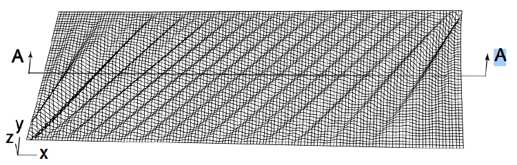
Figure 6 shows the overall, final wrinkle pattern in the membrane. The wrinkles in the central region are at 45◦ to the edges, but near the pair of corners that move closer together the wrinkles are “pinned” and hence form a kind of fan region.
This and the next 2 images are from:
Y. Wesley Wong and Sergio Pellegrino, “Wrinkled membranes Part iii: Numerical simulations”, Journal of Mechanics of Materials and Structures, Vol. 1, No. 1, January 2006
ABSTRACT: This is the third and final part of a study of wrinkles in thin membrane structures. High-fidelity, geometrically nonlinear finite element models of membrane structures, based on thin-shell elements, are used to simulate the onset and growth of wrinkles. The simulations are carried out with the ABAQUS finite element package. The accuracy of the results is demonstrated by computing the characteristics of the wrinkles in two specific membrane structures that were investigated experimentally and analytically in the first two papers in this series.
Page 9 / 360