|
|
||
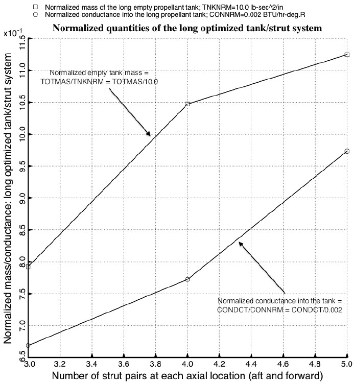
Fig. 32 from the 2013 GENOPT paper1.
Results from the specific cases called “test”, test3, etc: Optimized long propellant tank with two sets of struts, aft and forward. Shown here are the optimized empty tank mass and total conductance into the propellant tank as functions of the number of strut pairs at each axial location. Although the best design appears from this figure to have 3 pairs of struts at each axial location, note from Fig. 12 that in the “3-pair” optimized configuration the struts penetrate the wall of the propellant tank somewhat. Therefore, the configuration displayed in Figs. 5 and 6 (4 strut pairs at each axial location) is probably a better design even though the “4-pair” objective, WGT x (TOTMAS/TNKNRM) + (1 – WGT) x (CONDCT/CONNRM), is somewhat higher than the “3-pair” objective.
Page 112 / 190