|
|
||
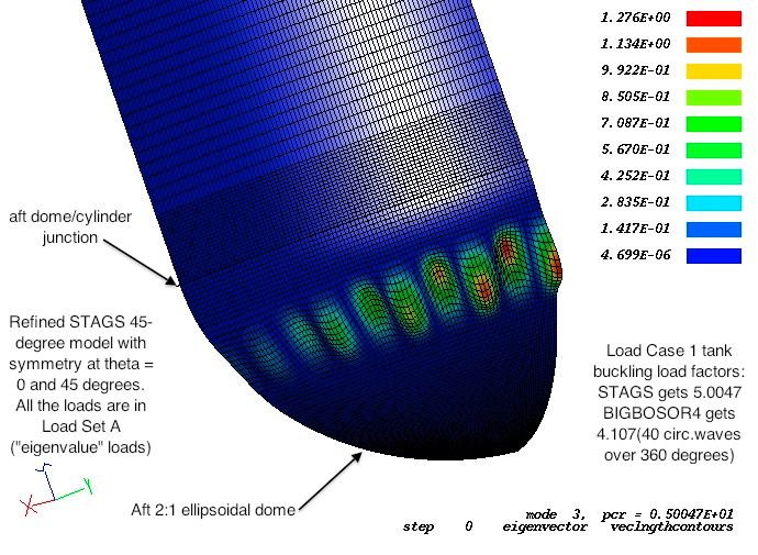
Fig. 31 from the 2013 GENOPT paper1. STAGS model of buckling of the propellant tank under Load Case 1 (10g axial acceleration plus 25 psi internal ullage pressure plus 200-degree tank cool-down). This is the same refined 45-degree STAGS model as that displayed in Fig. 26d except that this is a linear buckling model. In this STAGS model all the load components are in Load Set A (“eigenvalue” loads). There is no Load Set B. (For this problem it is very difficult to obtain with STAGS non-spurious buckling modes when there exist non-trivial loads in both Load Set A and Load Set B.) The struts shown in Fig. 26d are not shown in this view. In this STAGS model the fundamental (lowest) buckling load factor corresponding to buckling of the propellant tank is Buckling Mode No. 3. (The first two buckling modes involve buckling of the aft strut shown in Fig. 26d.) With all load components in Load Set A, BIGBOSOR4 obtains a buckling load factor of 4.107, which is somewhat lower than that predicted by this STAGS model (5.0047). The critical buckling mode according to BIGBOSOR4 is the same as that shown in Fig. 22. Note that this STAGS model predicts 5 full circumferential waves over 45 degrees of circumference, which is the same as the 40 circumferential waves that BIGBOSOR4 predicts over 360 degrees of circumference. As shown in Fig. 22, with only the loads associated with the 10g axial acceleration in Load Set A and the 25 psi ullage pressure plus 200-degrees tank cool-down in Load Set B, BIGBOSOR4 predicts a buckling load factor of 10.999.
Page 111 / 190