|
|
||
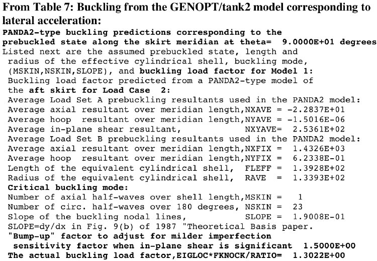
from Table 6 of the 2013 GENOPT paper2. Buckling of the aft skirt in the "twoskirt" model under Load Case 2 (10g lateral acceleration) corresponding to prebuckling conditions along the meridian at circumferential coordinate, theta = 90 degrees: In the PANDA-type Model 1 the conical skirts are modeled as “equivalent” cylindrical shells. For example, from the list shown here we see that the aft conical skirt is modeled as an equivalent cylindrical shell with length, FLEFF = 139.28 inches, and radius, RAVE = 133.93 inches. The uniform prebuckling resultants in the aft skirt are as follows:
Load Set A: (“eigenvalue” loads): NXAVE = -22.837 lb/in, NYAVE = -0.0000015, NXYAVE = 253.61 lb/in
Load Set B: (“fixed” loads): NXFIX = +1432.6 lb/in, NYFIX = +0.6233 lb/in, NXYFIX = 0.00 lb/in
The critical buckling mode:
(axial half waves over FLEFF=MSKIN, circ. half waves over 180 deg=NSKIN, slope of buckling nodal lines) = (1, 23, 0.19008)
The “equivalent” cylindrical shell of the forward skirt and its loading at theta = 90 degrees are similar to those of the aft skirt. According to the GENOPT/tank2 model, buckling of the forward skirt at theta = 90 degrees under Load Case 2 occurs at a slightly lower load factor, 1.2977, rather than 1.3022 listed here for the aft skirt.
The buckling load factor predicted for the aft skirt from the approximate PANDA-type theory is 1.3022, which is significantly lower than the buckling load factors displayed in Fig. 10(C) (the previous slide), which correspond to prebuckling loading along the meridian at circumferential coordinate, theta = 0.
It is this “shear” buckling at theta = 90 degrees in the forward skirt that gives rise to the eighth design margin listed in the "tank2" paper under Load Case 2 and repeated here:
8 -2.673E-02 (TNKBUK(2 ,2 )/TNKBUKA(2 ,2 )) / TNKBUKF(2 ,2 )-1; F.S.= 2.00
in which the meanings of “i” and “j” in TNKBUK(i, j) are: i = 2 means “Load Case 2”; j = 2 means “prebuckling conditions along the tank/skirt wall Meridian No. 2” (circumferential coordinate, theta = 90 degrees in this case). That eighth margin is computed as follows:
(buckling load factor) x (“bump-up” factor)/(factor of safety) – 1.0 = 1.2977 x 1.5/2.0 – 1.0 = -0.02673
The purpose of the “bump-up” factor listed here is to compensate for the use in the “tank2” formulation of a factor of safety (F.S.) for skirt buckling, THKBUKF = 2.0 (listed in Table 2) that is too high for the much milder sensitivity to initial imperfections of conical or cylindrical shells under primarily in-plane shear loading rather than uniform axial compression. In the “tank2” formulation we assume that an appropriate knockdown factor for shell buckling under primarily in-plane shear loading is 1/F.S. = 1/1.3333 rather than 1/2.0, which is more appropriate for axial compression of the laminated composite skirt configurations processed in this paper. The “Bump-up” factor is given by 2.0/1.3333 = 1.50 in this particular case (Load Case 2 loading at theta=90 deg.).
Compare the buckling load factor from this PANDA-type model corresponding to the prebuckling conditions along the skirt meridian at the circumferential coordinate, theta = 90 degrees (about 1.30) with those predicted from the STAGS model displayed on the next slide.
Page 137 / 190