|
|
||
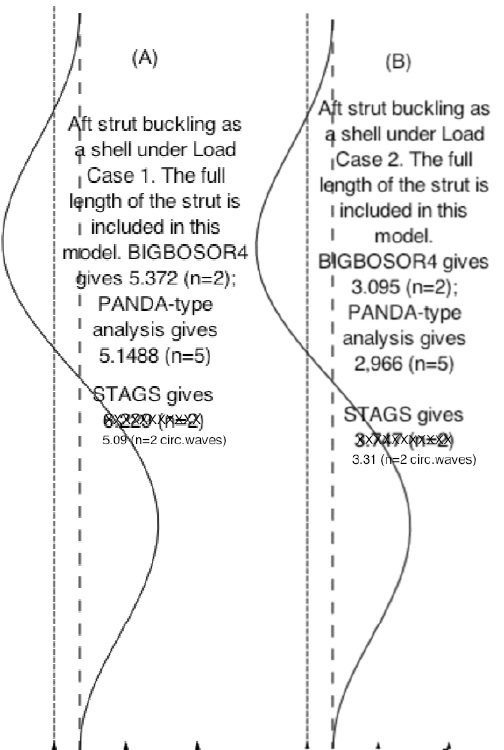
Fig 20 from the 2013 GENOPT paper1. Aft strut buckling mode shapes for the strut buckling as a thin shell rather than as a column. For computation of the design margin corresponding to buckling of the strut as a thin shell, GENOPT selects the lower of the load factors from the BIGBOSOR4 model and the PANDA-type model [15]. The strut shell buckling mode shapes displayed here are predicted by BIGBOSOR4 for the optimized long propellant tank with two sets of struts, aft and forward, 4 pairs of struts in each set. Buckling load factors from BIGBOSOR4 [2,3], from a PANDA-type of analysis [15] and from STAGS [16 – 19] are listed. The differences in the BIGBOSOR4 and STAGS predictions for the buckling load factors in (A) and (B) are primarily due to the different predictions from GENOPT/TANK and STAGS of maximum compressive load in an aft strut in Load Case 1 (axial acceleration): -22693 lbs according to GENOPT/TANK and -23082 lbs according to STAGS, and in Load Case 2 (lateral acceleration): -39393 lbs according to GENOPT/TANK and -35484 lbs according to STAGS. [See Table 7(b).]. The shell buckling modes shown in Parts (A) and (B) are from strut models that contain the entire length of the strut minus the lengths of the end fittings. The shell buckling modes shown in Parts (C) and (D) are from strut models that contain only 1/10th of that length. Notice that the buckling load factors predicted from the PANDA-type model are much less sensitive to the length of strut included in the strut shell buckling model than are the load factors predicted by BIGBOSOR4 and STAGS.
Page 101 / 190