|
|
||
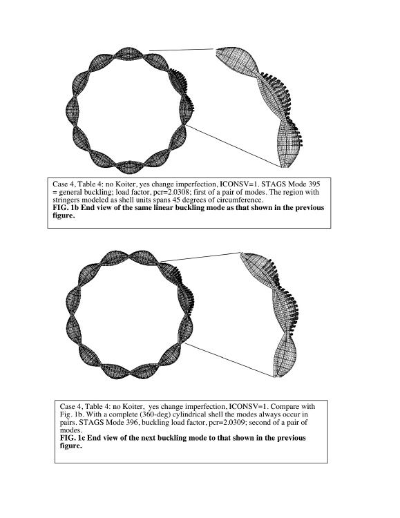
Shown in this slide are Fig. 1b and Fig. 1c of the 2007 Bushnell paper. Fig. 1b (top frame in the slide) is an end view of the same linear buckling mode as that shown in the previous figure. This buckling mode is the first of a pair of modes with essentially the same eigenvalue (buckling load factor).
The circumferential region in which each of the stringers is modeled as two shell units, one shell unit for the web of the T-shaped stringer and the other for the outstanding flange, is shown on the right-hand side. In this particular case this elaborately modeled region spans 45 degrees of the circumference of the cylindrical shell. The stringers are smeared out in the STAGS model of the rest of the circumference of the cylindrical shell.
The bottom frame in this slide shows Fig. 1c of the 2007 Bushnell paper. Shown here is an end view of the second of the pair of buckling modes.
Compare Fig. 1c with Fig. 1b (top figure).
With a complete (360-deg) STAGS model of a cylindrical shell the buckling eigenmodes always occur in pairs. The two buckling modes are the same except that one is shifted around the circumference by a quarter of a wavelength relative to the other of the pair.
Page 15 / 30