|
|
||
NASA Langley Research Center, Hampton, Virginia
Selected Publications:
J.G. Williams and R.C. Davis (NASA Langley Research Center, Hampton, Virginia, USA), “Experiments on stiffened conical shell structures using cast epoxy models”, Society for Experimental Stress Analysis, Fall Meeting, Indianapolis, Ind ; United States; 16-19 Oct. 1973. 38 pp. 1973
ABSTRACT: Description of a casting technique for fabricating high-quality plastic structural models, and review of results regarding the use of such specimens to parametrically study the effect of base ring stiffness on the critical buckling pressure of a ring-stiffened conical shell. The fabrication technique involves machining a metal mold to the desired configuration and vacuum-drawing the plastic material into the mold. A room-temperature curing translucent thermoset epoxy was the casting material selected. A shell of revolution computer program which employs a nonlinear axisymmetric prebuckling strain field to obtain a bifurcation buckling solution was used to guide the selection of congifurations tested. The shell experimentally exhibited asymmetric collapse behavior, and the ultimate load was considerably higher than the analytical bifurcation prediction. The asymmetric buckling mode shape, however, initially appeared at a pressure near the analysis bifurcation solution.
Agarwal, B. and Davis, R. C., "Minimum-Weight Designs for Hat-Stiffened Composite Panels under Uniaxial Compression," NASA TN D-7779, Nov. 1974.
Randall C. Davis and Paul A. Cooper (NASA Langley Research Center, Hampton, Virginia 23365, U.S.A.), “Interactive design of large end rings on stiffened conical shells using composites”, Computers & Structures, Vol. 4, No. 3, May 1974, pp. 647-650, IN1-IN2, 651-657, doi:10.1016/0045-7949(74)90012-1
ABSTRACT: Design study methods and results are presented of a composite reinforced base ring for the conical aeroshell structure of the planetary lander vehicle for Project Viking, an unmanned mission to Mars. The aeroshell is a ring and stringer-stiffened conical shell structure having a half angle of 70° with a large base ring mounted at the outer edge of the cone and a large pay-load ring in the interior with many smaller rings spaced along the inside shell surface. The purpose of the structure is to develop the aerodynamic drag required to decelerate the lander in the Mars atmosphere to facilitate a soft landing. The shell, therefore, must be designed to resist external pressure loads during Martian entry. Unlike conventional shell structures, the Viking aeroshell has no connecting supports at its large diameter edge and, therefore, it must resist the external pressure as an unsupported inertially loaded shell. Very little design information is available on large shell structures under these loading conditions. The structural weight of the aeroshell must be reduced to the minimum possible level while still retaining structural integrity. A currently proposed design for this structure is all metal, and the base ring accounts for 41 per cent of the total aeroshell structural weight. One possible method of reducing the weight of the proposed design is to selectively apply filamentary composites to reinforce a redesigned base ring. The filamentary reinforced base ring must be designed to take into account all possible modes of failure under the maximum design load conditions. The possible modes of failure are local or general buckling of the shell, ring buckling, and exceedence of the maximum permissible stress levels. The design of a shell structure of this complexity requires the use of the latest technology available in a large general purpose shell buckling program. A large general purpose non-linear shell buckling program developed by Lockheed (BOSOR 2) was used. Since the amount of computational effort is considerable for such a study, the turnaround time for using such a program as an aid in the design process was reduced by adapting the program to an interactive real time graphical system using the facilities of the Langley Research Center CDC computer complex. This paper describes the shell structure model and the stability results of a large Langley Research Center Viking aeroshell model, the BOSOR 2 computer program and its adaptation to an interactive system, and the design strategy used to re-design the base ring and the weight savings achieveable by composite reinforcements.
J. G. Williams and R. C. Davis, “Buckling experiments on stiffened cast-epoxy conical shells
A casting technique for manufacturing high-quality shell specimens with complex geometry is described and experimental and theoretical results are presented for a pressure-loaded ring-stiffened conical shell”, Experimental Mechanics, Vol. 15, No. 9, 1975, pp. 329-338, DOI: 10.1007/BF02318873
ABSTRACT: This paper describes a casting technique for fabricating high-quality plastic structural models and presents results on the use of such specimens to parametrically study the effect of base-ring stiffness on the critical buckling pressure of a ring-stiffened conical shell. The fabrication technique involves machining a metal mold to the desired configuration and vacuum drawing the plastic material into the mold. A room-temperature-curing translucent thermoset epoxy was the casting material selected. The casting technique allows many high-quality specimens to be produced and each specimen is capable of being repeatedly tested without failure. The conical shell was modified for successive tests by machining the epoxy base-ring configuration to reduce its stiffness. A shell-of-revolution computer program which uses a nonlinear axisymmetric prebuckling strain field to obtain a bifurcation-buckling solution was used to guide the selection of configurations tested. The shell experimentally exhibited asymmetric collapse behavior and the ultimate load was considerably higher than the analyticalbifurcation prediction. The asymmetric buckling-mode shape, however, initially appeared at a pressure near the analysis-bifurcation solution. Comparison of experimental and analytical prebuckling strains at pressure magnitudes below the initiation of asymmetric collapse showed good agreement.
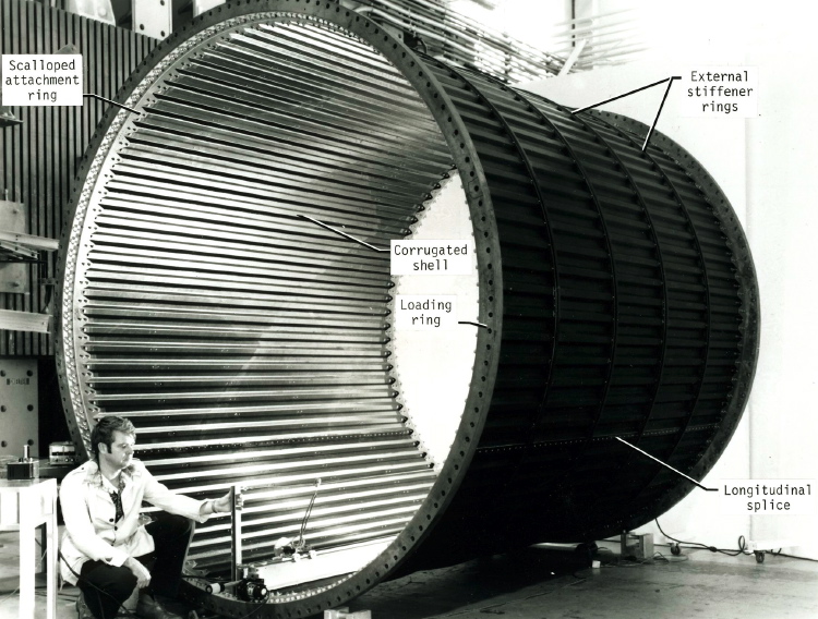
Randall C. Davis, “Buckling Test of a 3-Meter-Diameter Corrugated Graphite-Epoxy Cylindrical Shell”, NASA Technical paper, July 1982, proxy Url : http://handle.dtic.mil/100.2/ADA302796
ABSTRACT: A 3-m-diameter by 3-m-long corrugated cylindrical shell with external stiffening rings was tested to failure by buckling. The corrugation geometry for the graphite-epoxy composite cylinder wall was optimized to withstand a compressive load producing the relatively low maximum load intensity of 157.6 kN/m without buckling. The resulting mass per unit of shell-wall area, including stiffening rings and fasteners, 2 was 1.96 kg/sq m. The cylinder test-load achievement of 101 percent of design ultimate demonstrates a substantial mass-saving potential over available data for corrugated aluminum shell designs. Future space missions will require low-mass structures to achieve maximum payloads. For such structures that must carry compression loads without buckling, graphite-epoxy materials offer an attractive approach to providing the needed low-mass structural components. Preliminary design studies of lightly loaded shells, using minimum-mass structural-sizing codes, indicate that ring-stiffened graphite-epoxy corrugated shells can, like corrugated graphite epoxy panels offer a mass-saving potential of 20 to 40 percent over aluminum shell-wall design concepts. To evaluate the merits of a corrugated graphite-epoxy cylindrical shell and to develop a design data base for lightweight space structures, a program was initiated to design, fabricate, and test a 3-m-diameter by 3-m-long corrugated ring-stiffened graphite-epoxy cylinder. The preliminary design for the cylinder was generated using a minimum-mass structural-sizing code to carry an ultimate axial-compression loading intensity of 157.6 kN/m. The preliminary design for the shell was modified and verified by testing subcomponent specimens as described. The purpose of this paper is to present the results from the test of the cylinder.
Page 276 / 462