|
 |
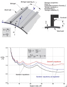 |
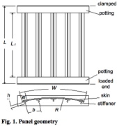
![Figure 1. Dimensions, geometry and lay-ups of stiffeners. Top: Panels PSC1–PSC9 [Abramovich et al. 2003], BOX1 and BOX2 [Abramovich et al. 2008]. Middle: Panels AXIAL1, AXIAL2, and BOX 3 [Degenhardt et al. 2006]](thumbnails/s123.jpg) |
 |
 |
|
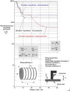
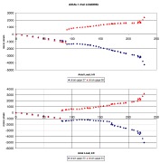
| Nondimensional buckling loads for external-hydrostatic-pressure-loaded ring-stiffened isotropic cylinders with R/h=500 and simply supported edges |
|
| Nondimensional buckling loads for compression-loaded stringer-stiffened isotropic cylinders with R/h=500 and simply supported edges |
|
| Figure 1. Dimensions, geometry and lay-ups of stiffeners. Top: Panels PSC1–PSC9 [Abramovich et al. 2003], BOX1 and BOX2 [Abramovich et al. 2008]. Middle: Panels AXIAL1, AXIAL2, and BOX 3 [Degenhardt et al. 2006] |
|
| Figure 3. Locations of strain gages and axial and lateral LVDT’s for panels AXIAL1 and AXIAL2. |
|
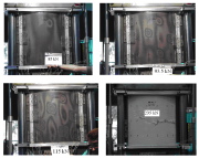
| Figure 4. Panel AXIAL1: Development of the buckling pattern as function of axial compression under 85 kN, 93.5 kN, and 115 kN, and after collapse at 235 kN. |
|
|
|
 |
 |
 |
 |
 |
|
| Figure 5. Panel AXIAL1: Strain gage readings versus axial compression. |
|
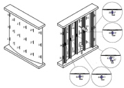
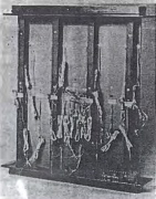
| Stiffened composite panel ready for testing under uniform end shortening |
|
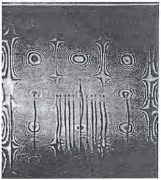
| Composite stiffened panel, locally buckled (that is, buckled between stringers) during the test under uniform end shortening |
|
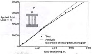
| Uniform end shortening versus total axial load, P, for the stiffened composite panel shown in the previous two slides |
|
| Cylindrical, stiffened, locally initially damaged composite panel to be axially compressed |
|
|
|
 |
 |
 |
 |
 |
|
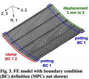
| Finite element model of the test specimen |
|
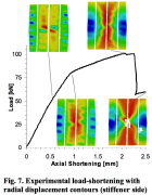
| Load-end-shortening for the test specimen |
|
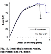
| Load-end-shortening curves from test and finite element model |
|
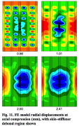
| Normal displacement contours from the finite element model for 4 values of end shortening (mm) |
|
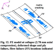
| Finite element model of the state of the panel at the collapse load |
|
|

