The purpose of GENOPT (GENeral OPTimization) is to enable an engineer to create a user-friendly system of programs for analyzing and/or optimizing anything. The application of GENOPT is not limited to the field of structural mechanics. GENOPT is designed to handle problems with small databases, not large finite element models, although it might well be used to provide a user-friendly "shell" within which any analysis could be done. GENOPT is ideal for generating programs for optimizing objects the behavior (stress, buckling, vibration, etc.) of which can be expressed by relatively simple tables or formulas such as those that appear in handbooks, or for optimizing objects the behavior of which has been previously encoded in existing subroutines. The optimizer used in GENOPT, created by Vanderplaats, is called ADS.
When engineers embark on the task of designing an object that must survive certain environments during service, they often develop or use computer programs that analyze given, fixed configurations. If, under the various applied loads, a configuration appears to be inadequate, the engineer changes certain dimensions, materials, or other parameters, and the analysis is repeated. The design evolves by means of this "manual" iterative process, which may require the expenditure of much labor and the passage of many days. Should a certain configuration prove satisfactory, that is, should the analysis program or programs show that this configuration survives all the environments with adequate margins of safety, the engineer is sorely tempted to terminate the iteration process and accept the design even though, while feasible, it may not be optimum.
The step from simple analysis to automated optimization seems to be a difficult one for many engineers and their managers. In every field there are many proven computer programs that analyze things with given configurations and given environments. Therefore, workers in a field are willing to accept the results of computerized analyses and to use these results as a basis for decisions on what to do next. However, these engineers and managers often seem less willing at present to allow the computer to make decisions about how the dimensions and other properties of the configuration are to be changed in order to minimize cost, minimize weight, or meet some other objective. Entering the field of automated optimization seems scary and appears to require mathematical expertise not available in time to meet the goals of a design project.
The main purpose of GENOPT is to make this step into the world of automated optimization easy. If the engineer has formulas from handbooks such as Roark's (1954), design curves, and/or algorithms for predicting the behavior of given configurations, GENOPT, working with these analysis tools, will generate a program system that can find the "best" design in a user-friendly way.
The user of GENOPT does not need to know much about optimization as a mathematical discipline. The optimizer used in GENOPT is called ADS, created by Vanderplaats (Vanderplaats and Sugimoto, 1986; Vanderplaats, 1987). ADS is "hardwired" in the "0-5-7" mode, which is the reliable "modified-method-of-feasible-directions" branch of this widely used optimization software.

Graphic from AIAA 52nd Structures, Structural Dynamics, and Materials Conference, 2011, AIAA Paper 2011-1811.
For the past 15 years Dr. David Bushnell has been doing research on the optimization of shells of revolution and prismatic panels and shells in which GENOPT has been used in combination with BIGBOSOR4 and HUGEBOSOR4. In these applications, cited in several papers below, GENOPT has successfully been used to solve optimizations in which there exist fairly large data bases. Hence, GENOPT works well when the analysis is more complicated than the "simple tables or formulas such as those that appear in handbooks..." mentioned near the end of the first paragraph above.
For a gallery of the kind of problem that can be solved by GENOPT, see the slide show that is primarily composed of pictures taken from the long, illustrated abstracts of papers about GENOPT and results generated from executions of GENOPT.
Abstracts and Papers
-
GENOPT – A Program That Writes User-Friendly Optimization Code, David Bushnell, Lockheed Palo Alto Research Laboratory, 3251 Hanover Street, Palo Alto, California 94304 USA. International Journal of Solids and Structures, Vol. 26. No. 9/10, pp. 1173-1210, 1990.
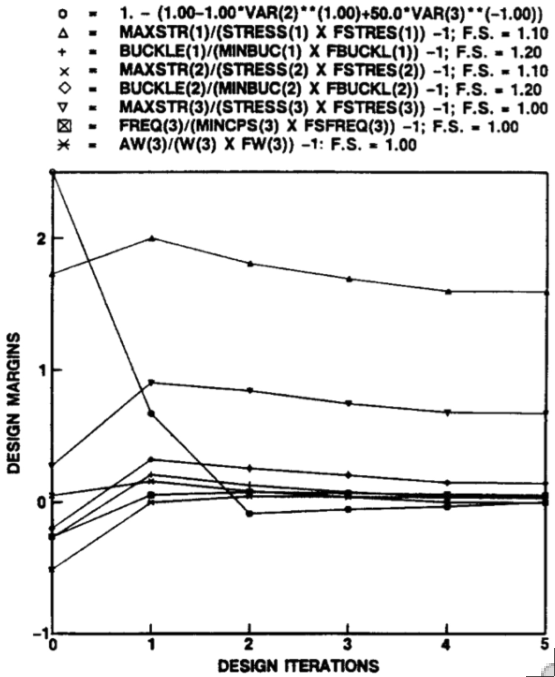
Minimum-weight design of a simply supported isotropic rectangular flat plate. This figure shows design margins versus optimization cycles. There are three design variables, thickness THICK, length, LENGTH and width, WIDTH. The plate is subjected to three load sets (k=1, 2 and 3) that involve three combinations of axial resultant Nx(k), in-plane shear resultant Nxy(k) and normal pressure, p(k). The plate is optimized by GENOPT subject to the following constraints: The maximum stress STRESS(k) times the factor of safety for stress FSTRESS(k) shall not exceed the allowable stress MAXSTR(k); the buckling load factor BUCKLE(k) shall be greater than the factor of safety for buckling FBUCKL(k) (MINBUC(k) = 1.0); the natural vibration frequency FREQ(k) shall be greater than the allowable frequency MINCPS(k) times the factor of safety for frequency FSFREQ(k); the maximum normal displacement W(k) under loading times the factor of safety for normal displacement FW(k) shall be less than the allowable normal displacement AW(k); and the area of the plate shall be greater than 50 units2. The objective is the weight of the plate: WEIGHT = density x THICK x LENGTH x WIDTH.
The purpose of GENOPT (GENeral OPTimization) is to enable an engineer to create a user-friendly system of programs for analyzing and/or optimizing anything. The application of GENOPT is not limited to the field of structural mechanics. GENOPT is designed to handle problems with small databases, not large finite element models, although it might well be used to provide a user-friendly "shell" within which any analysis could be done. GENOPT is ideal for generating programs for optimizing objects the behavior (stress, buckling, vibration, etc.) of which can be expressed by relatively simple tables or formulas such as those that appear in handbooks, or for optimizing objects the behavior of which has been previously encoded in existing subroutines. The optimizer used in GENOPT, created by Vanderplaats, is called ADS. GENOPT has been “hooked up” with BIGBOSOR4, an analyzer of shells of revolution and prismatic panels and shells.
-
SPHERE – A Program for Minimum Weight Design of Isogrid-Stiffened Spherical Shells Under Uniform External Pressure, David Bushnell, Department 93-30, Lockheed Palo Alto Research Laboratory, 3251 Hanover Street, Palo Alto, California 94304 USA. LMSC F372046, January 15, 1990.
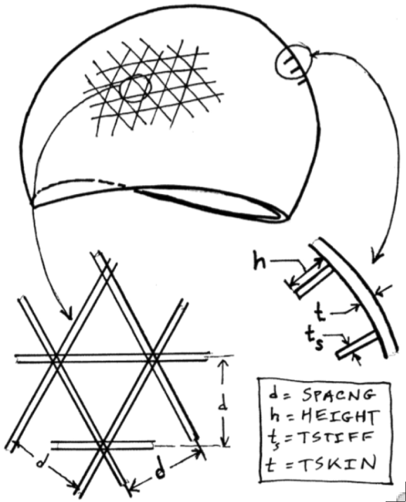
Optimization of a spherical shell with internal isogrid stiffening. The loading is uniform external pressure. The decision variables are d, h. ts and t. The shell shall not buckle in a general instability mode; the skin shall not buckle locally between stiffeners; the stiffeners shall not buckle; the stress in the skin shall be less than an allowable value; the stress in the stiffeners shall be less than an allowable value.
A system of programs called SPHERE has been developed for optimization of stiffened spherical shells under uniform external pressure. The stiffeners are assumed to be blades and are arranged in an isogrid pattern in order to maintain isotropy of the stiffened wall. In this way formulas and tables applicable to buckling of monocoque isotropic spherical shells can be applied, with proper definition of effective modulus and thickness, to buckling of stiffened spherical shells. Both the skin of the shell and the stiffeners are assumed to be of isotropic material, with different material properties in skin and stiffeners. Only membrane pre-buckling states are considered. The theory used follows, for the most part, that given by Meyer et al (1972), with the exception that skin and stiffeners may be of different material. The effect of transverse shear deformation is ignored. The effect of initial imperfections is included. An example is provided.
-
Automated Optimum Design of Shells of Revolution with Application to Ring-Stiffened Cylindrical Shells with Wavy Walls, David Bushnell, Senior Consulting Scientist, semi-retired, Dept. L9-24, Lockheed Martin Advanced Technology Center, 3251 Hanover St., Palo Alto, California 94304, USA. AIAA 41st Structures, Structural Dynamics, and Materials Conference, AIAA Paper 2000-1663, and Lockheed Martin Missiles & Space Company Report LMMS P525674, November, 1999.
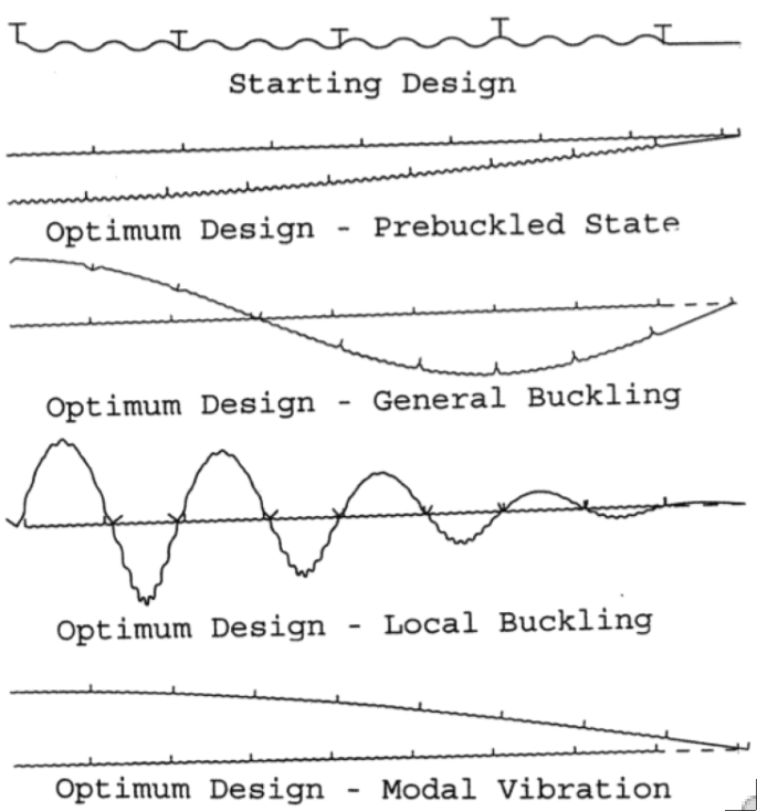
Optimization of an externally T-ring-stiffened cylindrical shell with a “wavy” wall. The loading is uniform external pressure. The beam-type lateral deflection at the midlength of the shell under random lateral shaking shall not exceed an allowable value; the shell shall not buckle generally; the shell shall not buckle locally; the natural vibration frequency shall be greater than a specified allowable frequency; the maximum stress shall not exceed an allowable value.
GENOPT, a program that writes user-friendly optimization code, and BIGBOSOR4, a program for stress, buckling, and vibration analyses of segmented, branched, stiffened shells of revolution, are combined to create a capability to optimize specific classes of shells of revolution. Examples are provided of aluminum cylindrical shells with wavy walls with and without ring stiffeners and a laminated composite cylindrical shell without rings. GENOPT and BIGBOSOR4 and recent improvements to them are described. In the examples the objective of the optimization is minimum weight and the design constraints involve stress, buckling, modal vibration, and random response to base excitation. An Appendix is provided in which a very simple example is used to demonstrate in detail how a user can create a capability to optimize any shell of revolution.
-
Minimum Weight Design of Imperfect Isogrid-Stiffened Ellipsoidal Shells Under Uniform External Pressure, David Bushnell, Fellow, AIAA, semi-retired, Palo Alto, CA 94303 USA. AIAA 50th Structures, Structural Dynamics, and Materials Conference, Palm Springs, California, 2009, AIAA Paper 2009-2702.
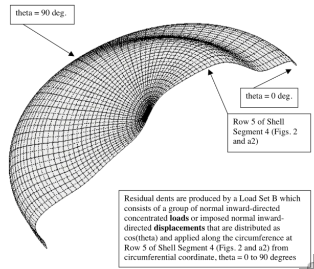
Left: A STAGS model of an ellipsoidal shell previously optimized by GENOPT/BIGBOSOR4; Right: Critical buckling mode of a different STAGS model of the same previously optimized ellipsoidal shell, this one initially dented.
GENOPT, a program that can be used to optimize anything, and BIGBOSOR4, a program for stress, buckling, and vibration analysis of segmented, branched, stiffened, elastic shells of revolution, are combined to create a capability to optimize a specific kind of shell of revolution: an internally isogrid-stiffened elastic ellipsoidal shell subjected to uniform external pressure. Optimum designs are obtained for isogrid-stiffened and un-stiffened axisymmetrically imperfect and perfect titanium 2:1 ellipsoidal shells. The decision variables are the shell skin thickness at several user-selected meridional stations, the height of the isogrid stiffeners at the same meridional stations, the spacing of the isogrid stiffeners (constant over the entire shell), and the thickness of the isogrid stiffeners (also constant over the entire shell). The design constraints involve maximum stress in the isogrid stiffeners, maximum stress in the shell skin, local buckling of an isogrid stiffener, local buckling of the shell skin between isogrid stiffeners, general nonlinear bifurcation buckling, nonlinear axisymmetric collapse, and maximum normal displacement at the apex of the dome. Optimum designs first obtained by GENOPT are subsequently evaluated by the use of STAGS, a general-purpose finite element computer program.
-
Use of GENOPT and BIGBOSOR4 to Obtain Optimum Designs of a Deep Submergence Tank, David Bushnell, Fellow, AIAA, semi-retired, Palo Alto, CA 94303 USA. Unpublished, un-numbered report, July 1, 2009.
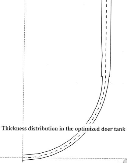
Axisymmetric deep submergence metallic tank with meridionally varying wall thickness optimized by GENOPT/BIGBOSOR4
The GENOPT/BIGBOSOR4 capability is used to obtain an optimum design of a titanium cylindrical tank with hemispherical ends. The tank is subjected to 15000 psi uniform external pressure. The objective of the optimization is to minimize the weight of the tank subject to stress and buckling design constraints. The decision variables establish the distribution of the shell wall material in a wide neighborhood of the junction between the hemispherical and cylindrical segments of the tank. The titanium is assumed to remain elastic. Creep is not included. The maximum allowable effective stress is assumed to by 120000 psi. A factor of safety of 1.3 is used for buckling and a factor of safety of 1.0 is used for stress. Enough detail is given so that an engineer or researcher other than the writer will be able to optimize similar shell structures with GENOPT/BIGBOSOR4.
-
Use of GENOPT and BIGBOSOR4 to Optimize Weld Lands in Axially Compressed Stiffened Cylindrical Shells and Evaluation of the Optimized Designs By Stags, David Bushnell, Fellow, AIAA, semi-retired, Palo Alto, CA 94303 USA, and Robert P. Thornburgh, U.S. Army Research Laboratory, Langley Research Center, Hampton, VA 23681-2199. AIAA 51st Structures, Structural Dynamics, and Materials Conference, 2010, AIAA Paper 2010-2927.
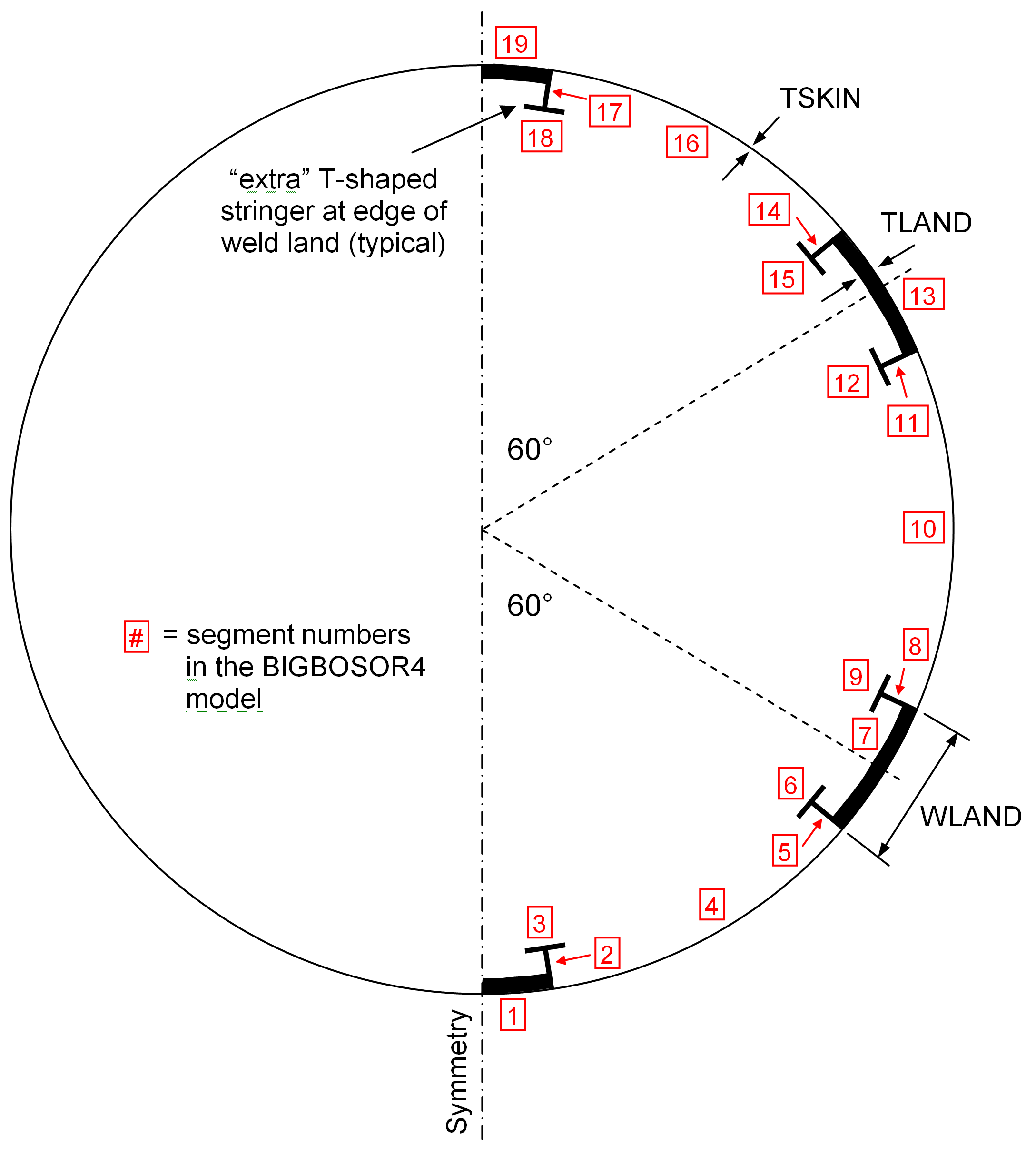
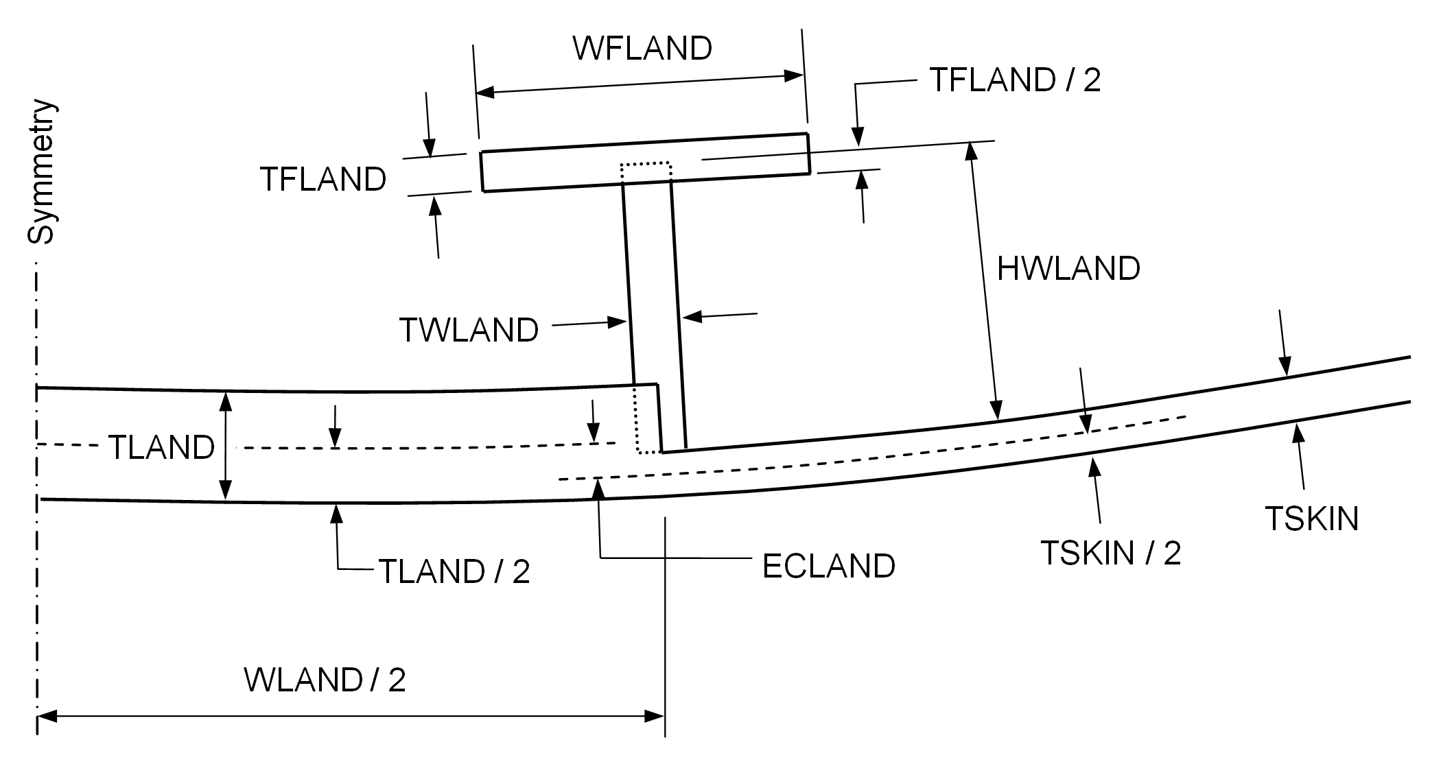
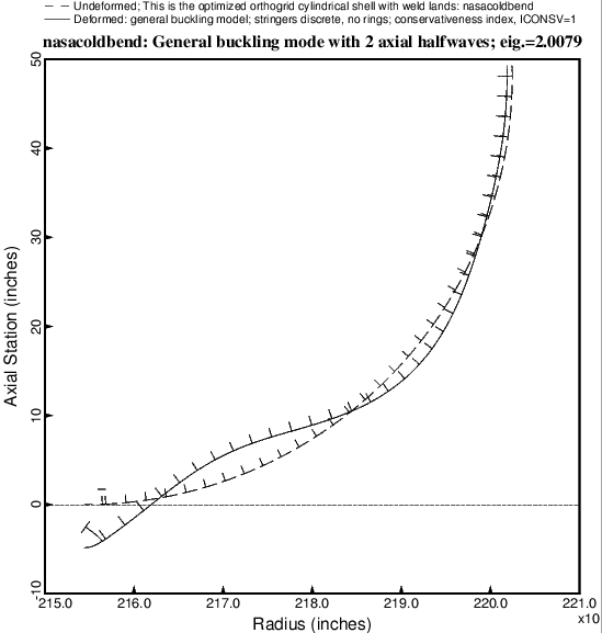
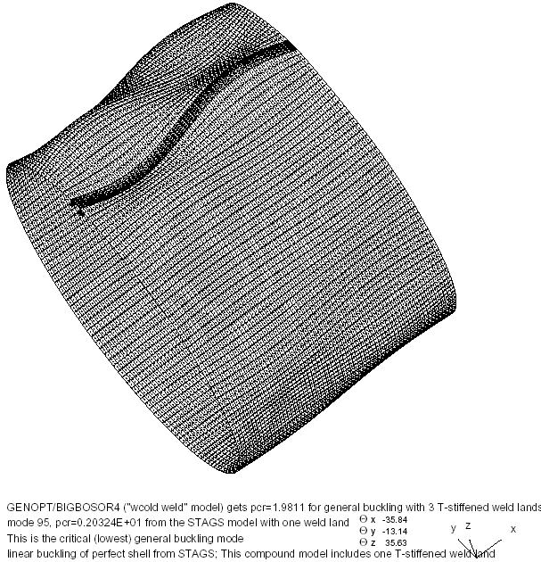
Upper Left: 180 degrees of a cylindrical shell with weld lands; Upper Right: Detail of a weld land with identification of the decision variables used for optimization; Lower Left: Buckling mode of a 90-degree prismatic BIGBOSOR4 model with a weld land at the bottom left; Lower Right: Buckling of an analogous STAGS model.
BIGBOSOR4 is used in an optimization loop in which the dimensions of a typical axially oriented weld land and the cross-section dimensions of reinforcing Tee-shaped stringers along the two straight edges (generators) of the weld land are decision variables. The optimization is carried out in a GENOPT context. Any number of equally spaced identical T-stiffened weld lands in a 360-degree cylindrical shell can be accommodated. The weld lands are embedded in an internally stiffened "acreage" cylindrical shell that has been previously optimized by PANDA2. The previously optimized "acreage" cylindrical shell has internal "acreage" stringers and internal "acreage" rings with rectangular cross sections. The spacings, heights, and thicknesses of the internal "acreage" stiffeners are not decision variables for the optimization problem in which the weld land and its reinforcing edge T-stringers are optimized. The design constraints for the cylindrical shell with the T-stiffened weld lands are: 1. general buckling, 2. inter-ring buckling, and 3. stress. The pre-buckled state is assumed to be uniform end shortening, with the membrane axial compression in each segment of the structure proportional to the axial membrane stiffness of that segment. The pre-buckled state is assumed to be a membrane state: no pre-buckling bending.
-
Use of GENOPT and BIGBOSOR4 to Obtain Optimum Designs of an Axially Compressed Cylindrical Shell with a Composite Truss-Core Sandwich Wall, David Bushnell, Fellow, AIAA, semi-retired, Palo Alto, CA 94303 USA, and Charles Rankin, Rhombus Consultants Group, Inc., Suite B100, 1121 San Antonio Rd., Palo Alto, CA 94303 USA. AIAA 52nd Structures, Structural Dynamics, and Materials Conference, 2011, AIAA Paper 2011-1811.
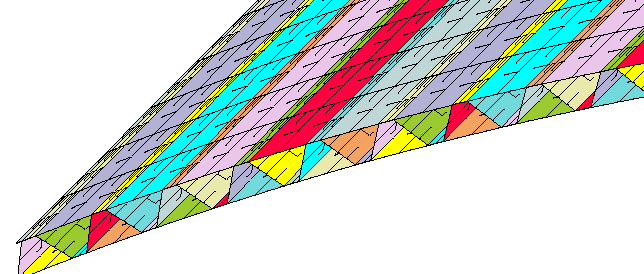
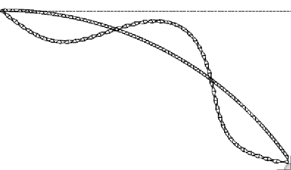
Left: STAGS model of part of a composite truss-core sandwich cylindrical shell under uniform axial compression previously optimized by GENOPT/BIGBOSOR4; Right: BIGBOSOR4 optimized model showing the critical buckling mode.
GENOPT/BIGBOSOR4 is applied to the problem of an axially compressed perfect elastic cylindrical shell the wall of which is a composite truss-core sandwich. The truss-core sandwich is constructed of trapezoidal core tubes that are sandwiched between two face sheets. At the junction of the core webs and the face sheets are “noodle” regions that are filled with unidirectional composite material. The design constraints are local buckling, general buckling, and five stress constraints for each material. Local and general buckling are computed from BIGBOSOR4 models in which the "huge torus" prismatic representation of the cylindrical shell is employed. In both the local and general buckling models the "huge torus" representation of the cylindrical shell consists of a number of identical modules of the cross section of the truss-core sandwich wall that are strung together along the curved meridian of the "huge torus". The rather elaborate 22-segment module used for local buckling includes small curved and straight segments that occur at the corners of the trapezoidal tool around which the truss-core is wrapped during the fabrication process. The presence of "noodles" that fill the prismatic triangular-like gaps between adjacent trapezoids is accounted for.
-
Use of GENOPT and BIGBOSOR4 to obtain optimum designs of multi-walled inflatable spherical and cylindrical vacuum chambers, David Bushnell, Fellow, AIAA, semi-retired, Palo Alto, CA 94303 USA, and Charles Rankin, Rhombus Consultants Group, Inc., Suite B100, 1121 San Antonio Rd., Palo Alto, CA 94303 USA. AAIA 53rd Structures, Structural Dynamics and Materials Meeting, Honolulu, Hawaii, AIAA Paper 2012-1416, April, 2012.
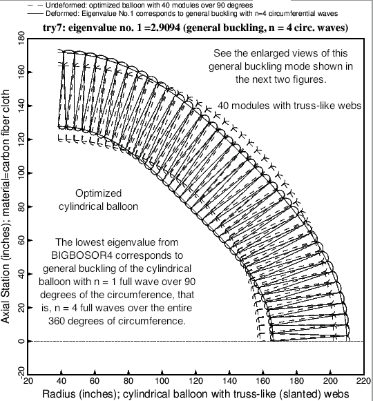
BIGBOSOR4 model of general buckling of an optimized truss-web sandwich balloon.
GENOPT/BIGBOSOR4 is applied to the problem of perfect elastic spherical or cylindrical “shells” (balloons) the complex inflatable wall of which is a webbed sandwich. The spherical or cylindrical balloon is stabilized by uniform pressure applied between its inner and outer walls and subjected to uniform pressure applied to its outermost wall. The distance between the inner and outer walls of the optimized spherical balloons is smaller than that for the optimized cylindrical balloons. The pre-buckling behavior of the spherical balloons is “crankier” (more nonlinear) than that of the cylindrical balloons with the result that certain special strategies have to be introduced in order to permit the generation of optimum designs via the GENOPT processor called SUPEROPT. General buckling modes of the type observed in optimized cylindrical balloons have so far not been observed in any spherical balloons, optimized or not. Local buckling modes include both axisymmetric modes and non-axisymmetric modes with many circumferential waves.
-
Optimization of Propellant Tanks Supported by Optimized Laminated Composite Tubular Struts, David Bushnell, Fellow, AIAA, semi-retired, Palo Alto, CA 94303 USA, Michael S. Jacoby, Senior Staff Engineer, Lockheed Martin Missiles and Space, Palo Alto, CA 94304, AIAA Member, and Charles C. Rankin, Rhombus Consultants Group, Inc., 1121 San Antonio Road, Palo Alto, CA 94303, AIAA Associate fellow. AIAA Paper 2013-1479, 54th AIAA Structures, Structural Dynamics and Materials Meeting, Boston, Massachusetts, April 8-12, 2013.
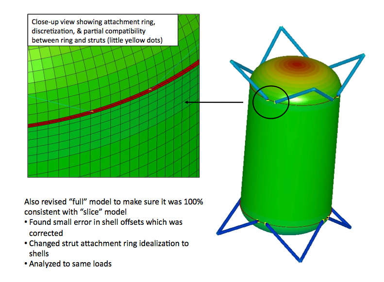
STAGS model of a strut-supported tank previously optimized by GENOPT/BIGBOSOR4.
The propellant tank is a shell of revolution completely filled with liquid hydrogen (LH2). This propellant tank is to be launched into space. During launch it is subjected to high axial and lateral accelerations. The tank is supported by a system of struts that consist mainly of tubes with laminated composite walls. This strut-supported tank system is optimized via GENOPT/BIGBOSOR4 in the presence of two loading cases:
- 10 g axial acceleration and 0 g lateral acceleration.
- 0 g axial acceleration and 10 g lateral acceleration.
In addition to the g-loading the tank has 25 psi internal ullage pressure and the tank wall is 200 degrees cooler than the wall of the launch vehicle from which it is supported by the struts.
In the BIGBOSOR4 modal vibration model the mass of the propellant is "lumped" into the tank wall, a conservative model. The tank/strut system is optimized in the presence of the following constraints:
- The minimum modal vibration frequency must be greater than a given value.
- Five stress components in each ply of the laminated composite wall of the strut tubes shall not exceed five specified allowables.
- No strut tube shall buckle as a column.
- No strut tube shall buckle as a thin cylindrical shell.
- The maximum effective (vonMises) stress in the tank wall shall not exceed a specified value.
- The tank wall shall not buckle.
- The maximum force in a strut during the launch-hold phase of a mission shall not exceed a specified value.
The objective to be minimized is in general a weighted combination of the normalized mass of the empty tank plus the normalized conductance of the support system: Objective= W x (normalized empty tank mass) + (1-W) x (normalized strut conductance), in which W is a user-selected weight between 0.0 and 1.0.
Two propellant tank/strut systems are optimized:
- A long tank with two "rings" of struts, an aft ring and a forward ring.
- A short tank with only one "ring" of struts.
It is emphasized that the tank/strut combination is optimized as a single system. The flexibility of the propellant tank is accounted for and found to be significant for optimized tank/strut systems. The flexibility of the launch vehicle to which the tank/strut system is attached is neglected: the ends of the supporting struts attached to the launch vehicle are assumed to be attached to rigid "ground".
Parameter studies are conducted in which optimum designs are obtained as a function of the number of strut pairs attached to the tank. During optimization linear theory is used throughout. Predictions for certain of the optimized tank/strut designs obtained here are compared with those from the general-purpose finite element code, STAGS. The agreement between the predictions of GENOPT/BIGBOSOR4 and STAGS qualifies the use of GENOPT/BIGBOSOR4 for preliminary design in the particular cases studied here.
-
Optimization of Propellant Tanks Supported by One or Two Optimized Laminated Composite Skirts, David Bushnell, Fellow, AIAA, semi-retired, Palo Alto, CA 94303 USA, Michael S. Jacoby, Senior Staff Engineer, Lockheed Martin Missiles and Space, Palo Alto, CA 94304, AIAA Member, and Charles C. Rankin, Rhombus Consultants Group, Inc., 1121 San Antonio Road, Palo Alto, CA 94303, AIAA Associate fellow. AIAA Paper 2013-1480, 54th AIAA Structures, Structural Dynamics and Materials Meeting, Boston, Massachusetts, April 8-12, 2013.
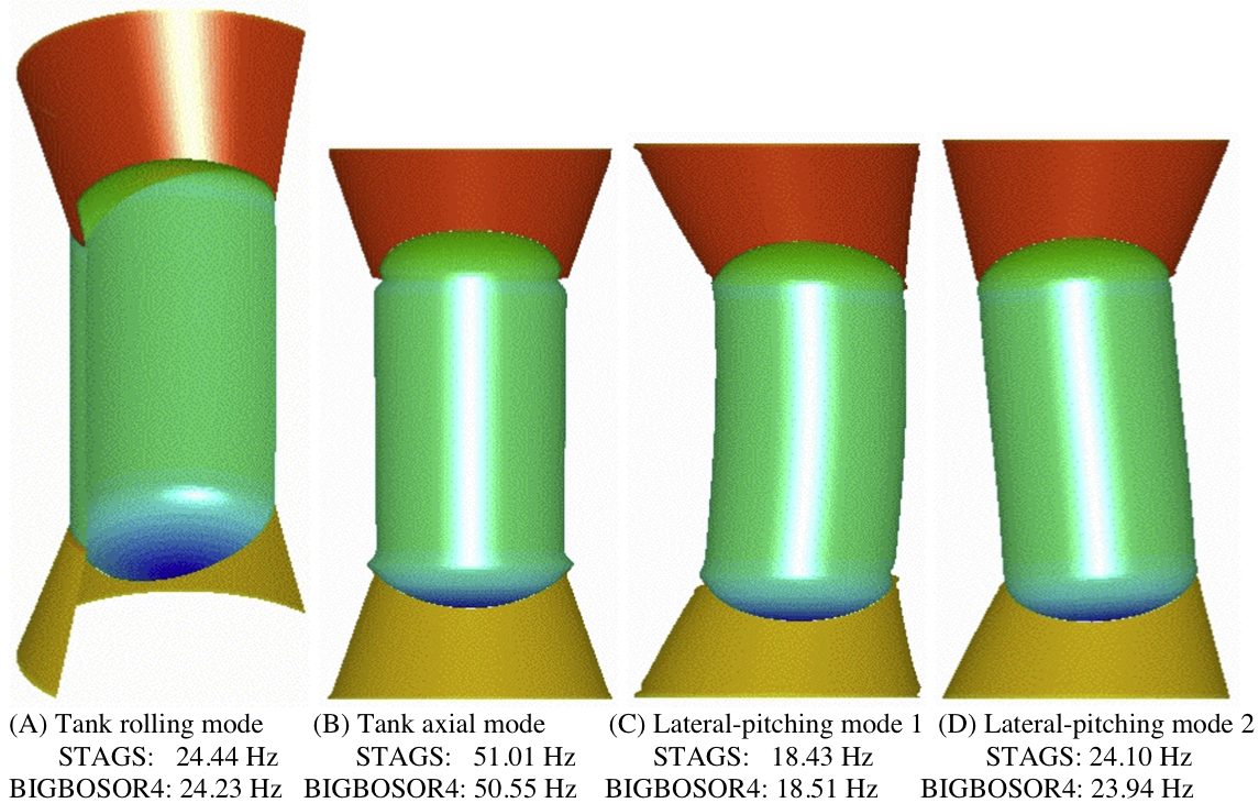
STAGS model of modal vibration of a skirt-supported tank previously optimized by GENOPT/BIGBOSOR4
The propellant tank is a shell of revolution completely filled with liquid hydrogen (LH2). This propellant tank is to be launched into space. During launch it is subjected to high axial and lateral accelerations.
The tank is supported by one or two conical skirts each of which consists of five segments: two short segments near each end of the skirt and a central long segment that has a laminated composite wall. Each of the short segments nearest the ends of the skirt has an isotropic one-layered wall with tapered thickness. Each short segment next to each short end segment is multi-layered with the extreme layers consisting of tapered isotropic material and the remaining internal, contained layers consisting of the same laminated composite wall as the long central segment.
This tank/skirt system is optimized via GENOPT/BIGBOSOR4 in the presence of two loading cases:
- 10 g axial acceleration and 0 g lateral acceleration.
- 0 g axial acceleration and 10 g lateral acceleration.
In addition to the g-loading the tank has 25 psi internal ullage pressure, the tank wall is 200 degrees cooler than the wall of the launch vehicle from which it is supported by the conical skirt(s), and there exists axisymmetric meridionally non-uniform cooling of the skirts. In the BIGBOSOR4 modal vibration model the mass of the propellant is "lumped" into the tank wall, a conservative model.
The tank/skirt system, a multi-segment branched shell of revolution, is optimized in the presence of the following constraints:
- The minimum modal vibration frequency of the tank/skirt(s) system must be greater than a given value.
- Five stress components in each ply of the laminated composite wall of the conical skirt(s) shall not exceed five specified allowables.
- The conical skirt(s) shall not buckle.
- The maximum effective (von Mises) stress in the tank wall shall not exceed a specified value.
- The tank wall shall not buckle.
The objective to be minimized is in general a weighted combination of the normalized mass of the empty tank plus the normalized conductance of the support system: Objective = W x (normalized empty tank mass) + (1-W) x (normalized strut conductance), in which W is a user-selected weight between 0.0 and 1.0.
Two propellant tank/skirt systems are optimized:
- A long tank with only one supporting skirt joined to the tank at the midlength of the tank.
- The same long tank with two supporting skirts, an aft skirt and a forward skirt.
It is emphasized that the tank/skirt(s) combination is optimized as a single branched shell of revolution. The flexibility of the launch vehicle to which the tank/skirt(s) system is attached is neglected: the ends of the supporting skirt(s) attached to the launch vehicle are assumed to be attached to rigid "ground".
Linear theory is used throughout. Predictions for the optimized tank/skirt designs obtained here are compared with those from the general-purpose finite element code, STAGS. The agreement between the predictions of GENOPT/BIGBOSOR4 and STAGS qualifies the use of GENOPT/BIGBOSOR4 for preliminary design in the particular cases studied here.
-
Minimum weight design of an axially compressed isotropic prismatic panel consisting of a series of cylindrical segments and verification by STAGS, David Bushnell, Fellow, AIAA, semi-retired, Palo Alto, CA 94303 USA and Michael S. Jacoby, Senior Staff Engineer, Lockheed Martin Missiles and Space, Palo Alto, CA 94304, AIAA Member. AIAA Paper 2014-0844, 55th AIAA Structures, Structural Dynamics and Materials Meeting, (Part of SCITECH2014), National Harbor, Maryland, January 13-17, 2014.
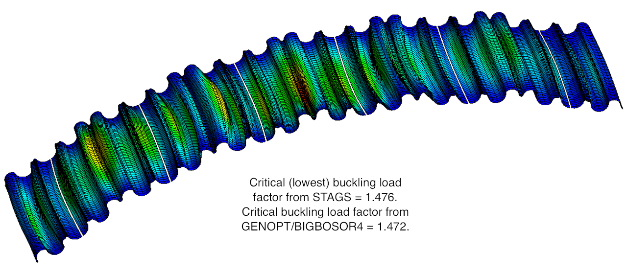
Buckling of an axially compressed, optimized, complexly corrugated cylindrical shell
We want to determine the minimum amount of material required to span a distance of width = WIDTH for an axially compressed, unstiffened, prismatic metallic wall or panel of length = LENGTH. The prismatic panel has a complex “corrugated” cross section. The width of the complex “corrugated” panel is composed of a number of “major” cylindrical segments, each of which may be divided into a number of cylindrical “sub-segments”. Each segment and each sub-segment is a sector of a little cylindrical shell the generators of which run in the axial direction. In addition there exists an overall arching over the entire width of the panel. The several little cylindrical segments/sub-segments are joined generator to generator in series. The entire unstiffened “corrugated” panel can be fabricated without any welding. Half of the width of the panel is included in the BIGBOSOR4 model used for optimization, with symmetry and anti-symmetry conditions imposed at its mid-width, WIDTH/2. The GENOPT/BIGBOSOR4 system is used to build the model and to perform the optimization. The minimum weight of the panel is determined in the presence of the following behavioral constraints:
- The panel shall not buckle locally.
- The panel shall not buckle in a general mode that is symmetric at the plane of symmetry.
- The panel shall not buckle in a general mode that is anti-symmetric at the plane of symmetry.
- Each little cylindrical segment of the panel shall not buckle in a “classical” mode.
- The maximum stress in the wall of the panel shall be less than a specified value.
The numerical analysis is extended to flat or curved panels of any width with repeating complex cross sections. An optimized cross-section profile with reflected and multiple repeating complex sections is mapped onto a cylindrical surface, and the buckling characteristics and weight of this complexly corrugated cylindrical shell are compared with those of an optimized “equivalent” cylindrical shell with external T-shaped stringers, an “equivalent” optimized cylindrical shell with a truss-core sandwich wall, and an optimized “equivalent” cylindrical shell with uniform corrugations.
It is found that the optimized complexly corrugated cylindrical shell weighs less than these other three optimized “equivalent” cylindrical shells that have different wall constructions. Optimized complexly corrugated panels with cylindrical segments the geometry of which varies across its width weigh about 12-14 per cent less than optimized uniformly corrugated panels, such as a standard corrugated panel.
The existence of sub-segments does not lead to panels that weigh less than panels without sub-segments. The gradient-based optimizer used in the GENOPT/BIGBOSOR4 system (“ADS” by Vanderplaats) has difficulty finding “global” optimum designs for panels with many cylindrical segments. One of the optimized designs determined with GENOPT/BIGBOSOR4 is verified by comparison with predictions from the general-purpose computer program STAGS. The agreement between the predictions of GENOPT/BIGBOSOR4 and STAGS qualifies the use of GENOPT/BIGBOSOR4 for optimization in the particular cases studied here. The behavior of optimized configurations with “corners” (discontinuous slope in the “width-wise” direction) between major cylindrical segments are compared with that of configurations in which these “corners” have been smoothed by the introduction of transitional fairing segments.
A program called HUGEBOSOR4 is developed to handle cases with up to 2950 segments.
-
Minimum weight design by GENOPT/BIGBOSOR4 of an externally pressurized circumferentially corrugated cylindrical shell and verification by STAGS, David Bushnell, Fellow, AIAA, Retired, Palo Alto, CA 94303 USA, email: bush@sonic.net. AIAA Paper 2015-xxxx, 56th AIAA Structures, Structural Dynamics and Materials Meeting, Kissammee, Florida, January 5-9, 2015. (The paper was withdrawn by the author because of lack of ability to speak clearly due to oro-mandibular dystonia.)
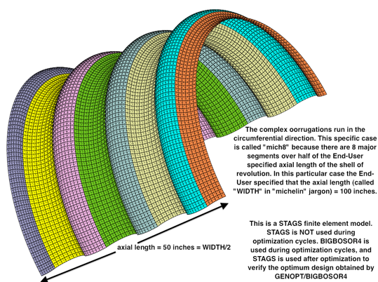
Circumferentially complexly corrugated shells of revolution subject to uniform external normal pressure
The results reported here are analogous to those reported in a previous paper on minimum weight design of elastic axially compressed prismatic complexly corrugated panels and shells in which the corrugations, each of which is a little cylindrical segment, run in the longitudinal direction. Here the corrugations, each of which is a little toroidal segment, run in the circumferential direction.
The complexly corrugated shell of revolution is loaded by uniform external lateral normal pressure. There is no axial load component equal to pr/2, and the shell of revolution is free to expand or contract in the axial direction as the external pressure is applied.
As before, the GENOPT/BIGBOSOR4 system is used to build the model and to perform the optimization. The minimum weight of the circumferentially corrugated shell is determined in the presence of the following behavioral constraints:
- The shell shall not buckle locally.
- The shell shall not buckle in a general mode that is symmetric at the plane of symmetry.
- The shell shall not buckle in a general mode that is anti-symmetric at the plane of symmetry.
- The maximum effective stress in the wall of the shell shall be less than a specified value.
“Corners” at junctions between adjacent toroidal segments are eliminated by the automatic insertion of small “smoothing” toroidal segments. The circumferentially corrugated shells are optimized with and without the inclusion of nonlinear geometric effects, and it is found that these nonlinear effects are significant.
Optimized designs are extremely sensitive to small changes in certain of the decision variables, making it difficult to find “global” optimum designs, especially when nonlinear theory is used. Several optimized designs determined with GENOPT/BIGBOSOR4 are verified by comparison with predictions from the general-purpose computer program STAGS. The agreement between the predictions of GENOPT/BIGBOSOR4 and STAGS is always good when linear theory is used, good for local buckling when either linear or nonlinear theory is used and fair for general buckling when nonlinear theory is used. There is always good agreement between BIGBOSOR4 and STAGS for the prediction of axisymmetric pre-buckling maximum effective stress.
-
Additional GENOPT documents
- Scope – A summary of what GENOPT does.
- Runstream – A sample runstream of GENOPT.
- Prismatic Model – Comparison of a "huge torus" model with a true prismatic shell model for:
- An axially compressed simple monocoque cylindrical shell.
- An axially compressed optimized truss-core sandwich cylindrical shell.
- An axially compressed optimized internally ring and stringer stiffened cylindrical shell with a T-stiffened weld land.
