|
 |
 |
 |
 |
 |
|
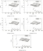
| Convergence of vibration frequencies and modes with increaseing number of degrees of freedom (DOF) in the model |
|
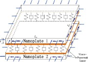
| Nonlocal vibration and biaxial buckling of double-viscoelastic-FGM-nanoplate system with viscoelastic Pasternak medium in between |
|
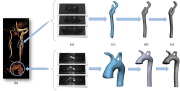
| Top: Carotid bifurcation; Bottom: Aortic arch |
|
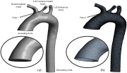
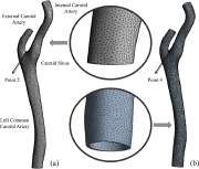
| Fluid and solid finite element models of the left carotid artery |
|
| Fluid and solid finite element models of the internal carotid artery |
|
|
|
 |
 |
 |
 |
 |
|
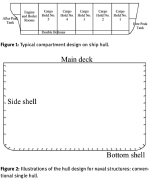
| Ship with cargo holds and typical single hull stiffened shell configuration |
|
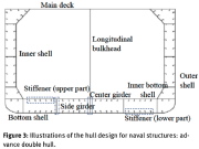
| Typical double hull stiffened shell configuration |
|
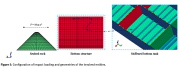
| Finite element models of seabed rock and stiffened bottom tank of a ship |
|
| Piping system with fluid flow |
|
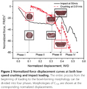
| Axial compression load-displacement curves for both low-speed crushing and impact of a buckyball |
|
|
|
 |
 |
 |
 |
 |
|
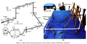
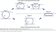
| Schematic of axial low-speed crushing and impact loading of a spherical shell (buckyball) |
|
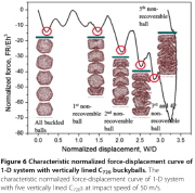
| Axial impact of a stack of 5 buckyballs |
|
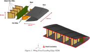
| Wing leading edge. Damage to the leading edge is shown in the next image. |
|
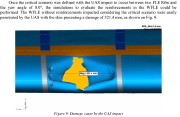
| Detail of the damage of part of the leading edge of the wing |
|
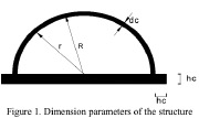
| Geometry of the shell structure to be buried |
|
|

