|
 |
 |
 |
 |
 |
|
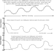
| Example 11, Slide 10: Starting design and optimized designs of a corrugated panel with sub-segments |
|
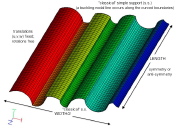
| Example 11, Slide 11: STAGS finite element model of the same panel previously optimized by GENOPT/BIGBOSOR4 |
|
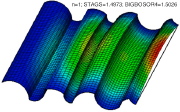
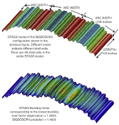
| Example 11, Slide 12: Lowest buckling mode from the STAGS finite element model shown in the previous slide |
|
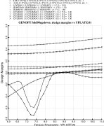
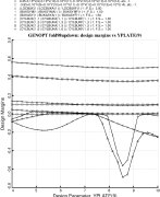
| Example 11, Slide 13: Sensitivity of the optimized design to one of the decision variables, YPLATE(8) |
|
| Example 11, Slide 14: Sensitivity of the optimized design to another of the decision variables, YPLATE(9) |
|
|
|
 |
 |
 |
 |
 |
|
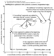
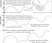
| Example 11, Slide 15: Strategy for "smoothing" a cross-section profile with corners |
|
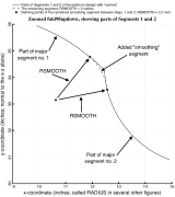
| Example 11, Slide 16: Zoomed view of the strategy for "smoothing" a cross-section profile with corners |
|
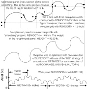
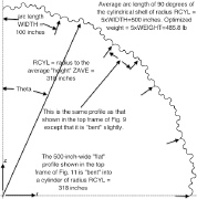
| Example 11, Slide 17: Smoothing strategy, optimized smoothed cross section, extended panel |
|
| Example 11, Slide 18: Optimization of a panel with shallower cylindrical segments. This panel can be fabricated by stamping |
|
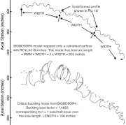
| Example 11, Slide 19: The optimized "flat" panel shown 10 slides ago is mapped onto a cylindrical surface |
|
|
|
 |
 |
 |
 |
 |
|
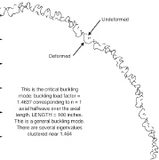
| Example 11, Slide 20: General buckling mode of the mapped corrugated cylindrical shell |
|
|
|
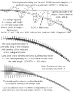
| Example 11, Slide 23: Buckling of optimized axially compressed aluminum cylindrical shell with external T-shaped stringers |
|
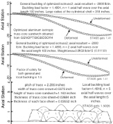
| Example 11, Slide 24: Buckling of optimized axially compressed aluminum cylindrical shell with a truss-core sandwich wall |
|
|