|
 |
 |
 |
 |
 |
|
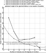
| EXAMPLE 8, Slide 7: Optimized weight of spherical balloons of fictitious carbon fiber cloth versus the number of modules over 90 meridional degrees |
|
| EXAMPLE 8, Slide 8: Design margins for an optimized spherical balloon made of fictitious carbon fiber cloth |
|
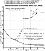
| EXAMPLE 8, Slide 9: Optimized weight of cylindrical balloons of fictitious carbon fiber cloth versus the number of modules over 90 circumferential deg |
|
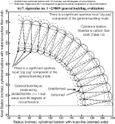
| EXAMPLE 8, Slide 10: General buckling of optimized cylindrical balloon with 15 truss-like modules over 90 degrees of circumference |
|
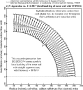
| EXAMPLE 8, Slide 11: Local buckling of optimized cylindrical balloon with 40 truss-like modules over 90 degrees of circumference |
|
|
|
 |
 |
 |
 |
 |
|
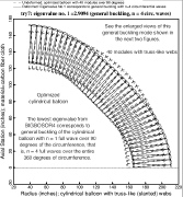
| EXAMPLE 8, Slide 12: General buckling mode of optimized cylindrical balloon with 40 truss-like modules over 90 degrees of circumference |
|
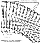
| EXAMPLE 8, Slide 13: Close-up view of the same buckling mode as that shown in the previous slide |
|
| EXAMPLE 9, Slide 1: OPTIMIZATION OF PROPELLANT TANKS SUPPORTED BY OPTIMIZED LAMINATED COMPOSITE TUBULAR STRUTS |
|
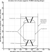
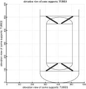
| Example 9, Slide 2: Starting design of a long propellant tank with two sets of supporting struts, aft & forward |
|
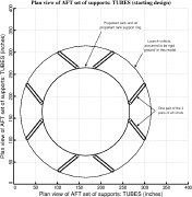
| Example 9, Slide 3: Plan view of the AFT set of strut supports for the starting design of the long propellant tank with aft & forward sets of struts |
|
|
|
 |
 |
 |
 |
 |
|
| Example 9, Slide 4: Propellant tank reinforcement at strut attachment point |
|
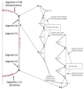
| Example 9, Slide 5: Propellant tank BIGBOSOR4 segments and aft and forward tapered double plus ring reinforcement |
|
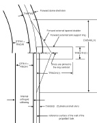
| Example 9, Slide 6: Forward part of propellant tank showing inner orthogrid "layer", shell wall layer, external tapered doubler and support ring |
|
| Example 9, Slide 7: Optimized design of a long propellant tank with two sets of supporting struts, aft & forward |
|
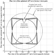
| Example 9, Slide 8: Plan view of the AFT set of strut supports for the optimized design of the long propellant tank with aft & forward sets of struts |
|
|