|
 |
 |
 |
 |
 |
|
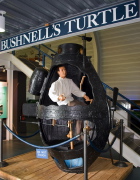
| The first submarine, invented by David Bushnell (1742-1824), was constructed circa 1776. The small submarine is a thin shell structure called "Turtle". |
|
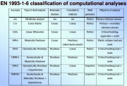
| Various types of analysis of thin steel shells according to Eurocode EN 1993-1-6 |
|
| Load-axial-end-shortening curves corresponding to various types of shell analysis defined in the previous image |
|
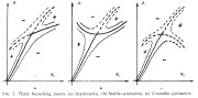
| Three types of equilibrium branching behavior |
|
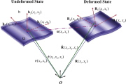
| undeformedand deformedstates |
|
|
|
 |
 |
 |
 |
 |
|
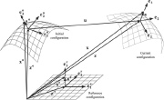
| Referene, Initial and Current configurations of a shell reference surface |
|
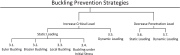
| Buckling prevention strategies |
|
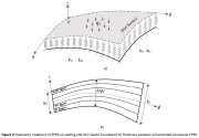
| Typical layup of a laminated composite plate or shell wall |
|
| Variable half-thickness of a laminated shell wall |
|
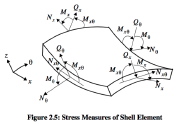
| Resultants acting on a shell wall element |
|
|
|
 |
 |
 |
 |
 |
|
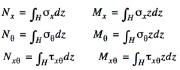
| Resultants are the integrals of stress components over the shell wall thickness, H |
|
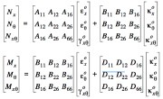
| Integrated stress-strain relations in a laminated composite shell wall, for example. |
|
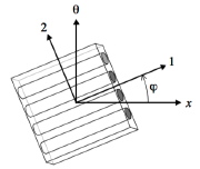
| This image represents a single layer in a shell wall. Shown are coordinate directions, "x" and "theta" (shell coordinates) and "1" and "2" (orthotropic material coordinates) |
|
| Transformation of stresses from material coordinates (the "1, 2" system) to shell coordinates (the "x,theta" system) |
|
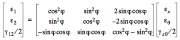
| Transformation of strains from material coordinates (the "1, 2" system) to shell coordinates (the "x,theta" system) |
|
|

