|
 |
 |
 |
 |
 |
|
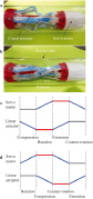
| Soft robot crawls along a pipe by ribbon buckling and twisting |
|
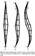
| (a) Finite element model and (b,c) Symmetric and antisymmetric buckling modes |
|
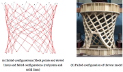
| Failure of axially compressed hyperboloid lattice "shell" from (a) simulation and (b) test |
|
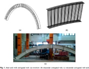
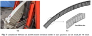
| Arch with corrugated web and test specimen |
|
| Local buckling of arch with corrugated web: (a) test result and (b) finite element model |
|
|
|
 |
 |
 |
 |
 |
|
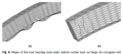
| Local buckling mode from the finite element model |
|
| Various origami structures |
|
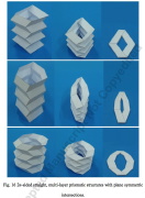
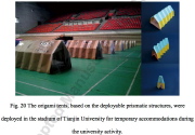
| Deployable thin-walled structures with various numbers of sides |
|
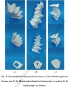
| Curved deployable thin-walled structures |
|
|
|
|
 |
 |
 |
 |
 |
|
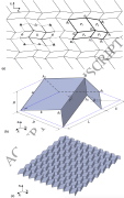
| (a) Miura-ori origami, (b) unit cell, and (c) sheet of unit cells |
|
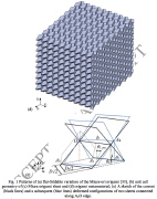
| Parts (d) and (e) of Fig. 1, (a-c) that are shown in the previous image |
|
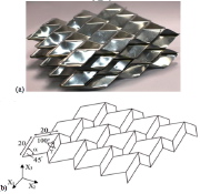
| Fig. 10 (a) Tested specimen; (b) Geometry of the individual sheets used to make the tested specimen; for (d) see the next image |
|
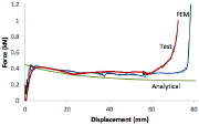
| Force-displacement curves from test and finite element (FE) model |
|
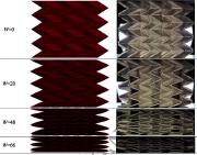
| Axial displaement W (mm) from the FE model (left side) and from the test (right side) |
|
|

