|
 |
 |
 |
 |
 |
|
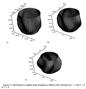
| Elastic-plastic thick cylindrical shell under bending: Predicted buckling modes for R/t = 10 |
|
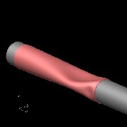
| Local buckling and large cross-section deformation of a laterally impacted long tube |
|
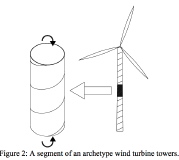
| Elastic buckling and collapse analysis of spirally welded circular hollow thin-walled sections, such as the base of a wind turbine tower |
|
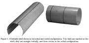
| A bistable shell shown in its initial and coiled configuration |
|
| Non-linear dynamics and stability of a circular cylindrical shells containing a flowing fluid |
|
|
|
 |
 |
 |
 |
 |
|
| Buckling of blood vessel with internal axial flow |
|
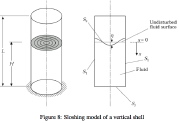
| Sloshing of fluid in a partly filled vertical cylindrical shell |
|
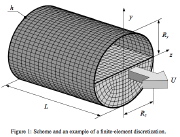
| Finite element model of pipe with oval cross section partially filled with flowing fluid. |
|
| Fluid-structure internaction: Underwater pipe surrounded by fluid |
|
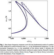
| Nonlinear harmonic forcing: frequency response curve for the fundamental mode of a perfect cylindrical shell |
|
|
|
 |
 |
 |
 |
 |
|
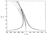
| Frequency-Response curves for nonlinear vibrations of a simply-supported cylindrical shell |
|
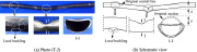
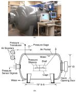
| Fig. 1 Custom pressure testing facility used to conduct implosion experiments. (a) Photograph and (b) scaled schematic. |
|
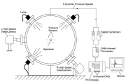
| Fig. 2 Cross section of pressure testing facility showing the illumination system, the high-speed video cameras, the pressure sensors and the data acquisition system. |
|
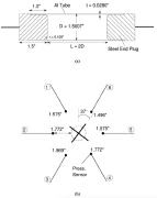
| Fig. 3 (a) Schematic of shell specimen geometry for IMP69. (b) Positions of mid-span pressure sensors. |
|
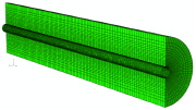
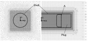
| Fig. 15. Truncated views of fluid Computational Fluid Dynamics (CFD) meshes for IMP69. |
|
|

